
Fusion splicing is the most widely used method of splicing as it provides for the lowest loss and least reflectance, as well as providing the strongest and most reliable joint between two fibers. Virtually all singlemode splices are fusion. There are two main methods of splicing: mechanical splicing and fusion splicing. This blog will delve into the nuances of each method, comparing their costs, labor efficiency, network performance, and more, to help you decide which splicing technique is best suited for your needs. Why splice? Fiber. Fusion splicing is the process of fusing or welding two fibers together usually by an electric arc. Fiber splicing means joining two optical fibers (permanently or temporarily) such that light guided in one fiber and reaching the joint (splice) can be transferred into the second fiber with low insertion loss. Another method of connecting optical fibers is termination or connectorization, which consists of processing the end of a fiber optic bundle so that it can be connected to other fibers or devices through fiber optic. Fiber Optic Cable is a form of modern network cable that has a far greater capacity than electrical communication connections. Splicing is typically required during cable installation, maintenance, or network expansion. The goal is to achieve the lowest possible optical loss (signal.
[PDF]

Optical fiber technology has revolutionized the way we communicate, enabling fast and reliable data transmission over long distances. In this article, we will explore the different types of optical fibers used in communication systems and their applications. Fiber Optics or Optical Fiber is a technology that transmits data as a light pulse along a glass or plastic fiber. An Optical Fiber is a cylindrical fiber of glass that is hair-thin in size or any transparent dielectric medium. The fiber which is used for optical communication is waveguides made of. Optical fibers are the backbone of modern communication. They transmit light signals over long distances with minimal loss. Let's break down their classification in a simple and engaging way: 1. The less signal damage metal wires can cause, the better for optical fiber connection. Total internal reflection (critical angle, using Snell's law). Higher bandwidth (extremely high data transfer rate). Less signal degradation. Less costly per meter. Lighter and thinner then copper wire. The light is a form of carrier wave that is modulated to carry information. The cladding's refractive index is slightly smaller than that of the core, which confines light within the core and propagates by repeated total reflection at the boundary with the.
[PDF]
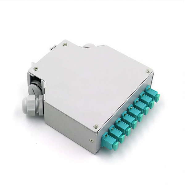
An Optical Distribution Frame (ODF) is a dedicated unit designed to organize, terminate, and interconnect fiber optic cables. It brings together fiber splicing, patching, and cable routing in a single structure, while shielding sensitive connectors and splices from mechanical. In the complex architecture of fiber optic networks, the Optical Distribution Frame (ODF) serves as the linchpin for organizing, protecting, and distributing optical signals. Whether in data centers, telecom central offices, or enterprise network rooms, ODFs enable efficient fiber management. Among the many solutions available, the Optical Distribution Frame (ODF) plays a central role in organizing, protecting, and simplifying fiber management in telecom rooms, central offices, and data centers. As data centers, enterprises, telecom operators, and smart-building infrastructures deploy increasingly dense fiber links, ODFs provide the structured. Optical Distribution Frames (ODF) are indispensable components in optical communications networks. They provide efficient fiber optic management, connectivity, and protection. Whether you are building a data center, deploying FTTx networks, or managing the telecom systems, the selection of suitable ODF is very important since the fiber connections are optimized.
[PDF]

To use a power meter for fiber optic testing, always clean connectors first with lint-free wipes or click-to-clean tools. Select the correct wavelength and set your reference. You measure optical power in dBm or insertion loss in dB. Consistent procedures ensure accuracy. Verify light travels from. The most basic fiber optic measurement is optical power from the end of a fiber. This measurement is the basis for loss measurements as well as the power from a source or presented at a receiver. Typically both transmitters and receivers have receptacles for fiber optic connectors, so measuring the. An optical power meter measures the strength of light traveling through a fiber optic cable, giving you a reading in dBm (decibels relative to one milliwatt). This article will guide you through the methods, instruments, and key considerations for measuring fiber. Fiber optic cabling is the high-performance core of today's datacom networks. As network speeds and bandwidth demands increase, fiber performance requirements have become more stringent. Fiber testing is more important than ever. An OPM uses a photodiode to generate an electrical current proportional to optical power.
[PDF]
Bulk purchases typically come with discounts, making it more cost-effective for large-scale projects. Conversely, single or small quantity orders may incur higher per-unit costs. As of recent market analysis, the price range for OPGW cables is generally between RMB 10,000 to RMB 30,000. Fiber-optic cable materials typically cost $1 to $6 per linear foot, depending on fiber count and cable type. Commercial building installations with 100-200 network drops generally range from $15,000 to $30,000. Single-mode fiber costs less per foot than multimode fiber, but it requires more. Large core fibers from Fibercore. Highly customizable designs with a wide range of coatings available. Offering unique properties and benefits for different types of use, 8 core armoured cable Fiber Optic om3 multimode. TMT GLOBAL Fiber Optic Cable offers a high-quality multimode 8. Large core multimode optical fiber with core diameters from 10 ~ 2000µm provide ease of alignment and enable light/laser transmission with high power efficiency. A wide variety of silica core and silica clad optical fibers to cover a broad spectrum of wavelength ranges from deep ultraviolet (DUV). 20-meter hdmi 2. 0v fiber optic cable designed for high-resolution video transmission. Fiber Visual Fault Locator,10KM VFL Fiber Optic Cable Tester,Network Fiber Cable Test Fiber Light. 5m mtp 10gb 50/125 om3 multimode pvc fiber optic cable - aqua.
[PDF]
Mid-Range — 2,000 ft outdoor run with conduit and 4 terminations: Cable $0. 60/ft, Permits $350, Delivery $120, Accessories $250. Total ≈ $4,940–$6,120. Multi-fiber cables worked as described and with no issues. Buy 4 Fibers OM3 Multimode PVC (OFNR) Indoor Tight Buffered Multifiber Pre-Terminated Cable at reliable fiber optic cable supplier, best price & Fast shipping. Typical rates range from $0. 00 per ft depending on terrain, access, and required precision for termination. Commercial building installations with 100-200 network drops generally range from $15,000 to $30,000. Single-mode fiber costs less per foot than multimode fiber, but it requires more. Aluminum Folding Telescopic Ladder 4. 4m for Home & Outdoor ₹ 6,550. 00 Original price was: ₹6,550. 4 Core FTTH Single Mode Optical Fiber Cable – Round OD 5. High quality fiber optic cables from Corning, AFL, OCC, Mohawk and other leading manufacturers. Aerial, ADSS, armored, distribution, direct burial and more. Pricing (USD) Filter the results in the table by unit price based on your quantity. A tariff of 8% may be applied if shipping to the United States.
[PDF]

Fiber optic network design (896. 83 KB). I'm needing symbols for common fiber optic components, cables, connectors, backbone ports, etc. Can anyone help me out? Some examples of a diagram would also help. 10-27-2018 01:41 AM Do you know if there's some symbol standard fir this kind of schematics? I surely don't know. If you can be helpful. Free CAD and BIM blocks library - content for AutoCAD, AutoCAD LT, Revit, Inventor, Fusion 360 and other 2D and 3D CAD applications by Autodesk. CAD blocks and files can be downloaded in the formats DWG, RFA, IPT, F3D. You can exchange useful blocks and symbols with other CAD and BIM users. See. Search by part number or description such as CAT5, CAT6, OSP, etc. Sort by any of the table headers. Use the drop down menu to filter by product category and type. Sort by any. Welcome to the Corning LANscape® Solutions Product Drawings Resource Center, your complete source for our optical hardware component drawings. The two-dimensional and isometric hardware products drawings are available in PDF (Adobe® Acrobat®), DXF (AutoCAD®), VSS (Visio® Stencil) formats, and. Be among the first to receive important product updates, insights and news. Of all these options, the most favored one is optical cables because they offer uninterrupted swift data transmission.
[PDF]

Manta HM (stands for "high magnification") is an automated microscope for inspection of single and multi-fiber patch cords, bulkhead and transceivers, including but not limited to: MT, MPO, SN-MT, MMC, LC, FC, SC, CS®, SN®, MDC, E2000™, MXC, PRIZM, QSFP, ARINC . Manta HM (stands for "high magnification") is an automated microscope for inspection of single and multi-fiber patch cords, bulkhead and transceivers, including but not limited to: MT, MPO, SN-MT, MMC, LC, FC, SC, CS®, SN®, MDC, E2000™, MXC, PRIZM, QSFP, ARINC . Image shown is a representation only. Exact specifications should be obtained from the product data sheet. Order today, ships today. F3-SDLCLC-HM – Cable Fiber Optic LC/UPC Duplex To LC/UPC Duplex 9/125 1. 64' (500mm) from CompuCablePlusUSA. Pricing and Availability on millions of electronic. Buy now, ships today. that performs on-site drawing of copper. When drawing copper, PCA starts with 13 AWG solid copper conductor on custom built deploying devices, called Stems. The copper is pulled into drawing. CESS, 3 HOLE OT P NG S, 3 HO.
[PDF]

Fiber Optic Welding How To Joint Fiber Optic Cablesplicing fiber optic cable,fiber optic splice,fiber optic,fiber optics,fiber splice,how to splice,fibre opt. The optical fiber connection adopts the fusion splicing method. The whole process is similar to the welding of metal wires, and it is generally carried out by electric isolation. At the moment, there are two methods of connection: Thermal welding of optical fibers consists in bringing the ends of the conductor to melting using a fiber optic splicer, and more specifically - located inside the electrodes. The welded ends are then pressed and a weld is formed. The most work is waiting for installers, whose tasks can be divided into several stages: In this part, we will deal with the second stage, i. welding, which is considered to be one of the most difficult parts of installers' work in. Open the stripping tube and wipe the grease on the optical fiber with toilet paper and alcohol cotton. On the welding disc, make the optical fiber precoil first and cut the optical fiber into an appropriate length to facilitate the coil fiber work after welding. Add heat shrink tube. Procedure. Another method is to use the so-called mechanical welding. It uses special parts that are prepared in advance to connect the two ends. Thanks to this, you can connect two ends of the cable with a ready-made splice, without the need to use an optical fiber splicer. While this method may appear to be.
[PDF]

Mechanical splicing is a fast way to join two fiber optic cables. Instead, you line up the fibers inside a small holder made of plastic or metal. The holder keeps the fibers steady. A special gel helps light move through the joint. In this guide, we'll walk you through exactly how to splice fiber without a fusion splicer, covering the tools you need, the step-by-step process, performance specs, and common mistakes to avoid. By the end, you'll be equipped to make clean, low-loss connections in any field scenario. Experts who add quality contributions will have a chance to be featured. Learn more Mechanical splicing is a. Executive Summary: A fiber optic pigtail is one of the most commonly specified yet least understood components in structured cabling. Get the wrong connector type, the wrong polish, or skip proper fusion splicing technique—and you're looking at elevated signal loss, increased back reflection, and a. Fiber optic cable splicing connects two cables, creating a strong link for fast data transmission. Fusion splicing uses heat to join fibers, while mechanical splicing aligns fibers without the need. This video will show you how to repair a damaged fiber optic cable strand without a fusion splicer. This temporary fix will get your network back up and running, giving you time to source new fiber cable. Fusion Splicing Fusion.
[PDF]

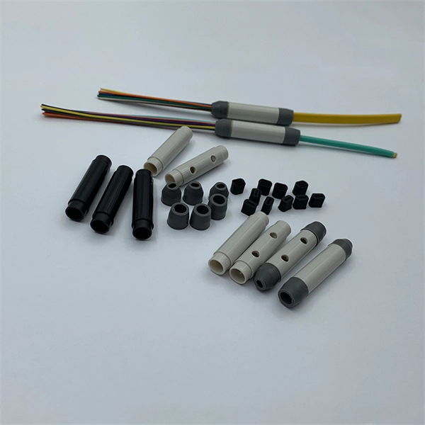
The most efficient way to terminate a fiber run is by using a pigtail. A fiber pigtail is a short length of optical fiber that comes with a high-quality, factory-polished connector already installed on one end, leaving a length of exposed glass on the other. Instead of building a connector from. Installing fiber optic pigtails correctly is essential for ensuring low signal loss and long-term reliability. Remove the outer coating carefully to expose the fiber. Use alcohol wipes to remove dust and debris. Make a precise cut for optimal splicing. Align and fuse the pigtail fiber with the main. Executive Summary: A fiber optic pigtail is one of the most commonly specified yet least understood components in structured cabling. Get the wrong connector type, the wrong polish, or skip proper fusion splicing technique—and you're looking at elevated signal loss, increased back reflection, and a. A fiber optic pigtail is a short length of optical fiber with a connector pre-attached to one end. If you're new to fiber optics or want to enhance your technical skills, this guide will help you understand how to splice fiber pigtails safely and efficiently. --- 🔧 In. Fusion splicing involves precisely melting the ends of two optical fibers together, creating a seamless connection that minimizes signal loss. This method offers the lowest attenuation and reflectance, making it ideal for long-haul telecommunications. You can buy this fusion splicing kit here On.
[PDF]

Contrary to popular belief, fiber optic cables do not contain copper. Instead, they consist primarily of glass or plastic fibers that transmit data using light signals. These fibers are surrounded by protective coatings made of materials such as polymer or epoxy resin. Fiber optic cables are designed to provide high-speed, no-signal-loss, and EMI-free communication in telecommunication, powergrid, datacenter, broadband, and industrial applications. Each optical cable is constructed using a precise combination of optical fibers, strength members, buffer tubes. Fiber optic cables use pulses of light through ultra-pure glass or plastic fibers to carry information rather than electrical signals. Cladding: Lower refractive index layer reflecting light back into. You might wonder if there's copper inside fiber optic cables. It's not a yes-or-no answer. So, it's about knowing the different types. Its primary method of data transmission relies on light signals traveling through glass or plastic fibers, rendering copper conductors unnecessary for that purpose. Fiber optic cables have revolutionized data transmission. The two core material technologies used in almost all cables are fiber optic, and copper wiring.
[PDF]

This practical file details experiments conducted in Optical Fiber Communication, covering modulation techniques, system components, and performance analysis. An optical fiber is a glass or plastic fiber designed to guide light along its length, widely used in fiber-optic communication, which permits transmission over longer distances and at higher data rates than other forms of communications. Fiber-optic communication is a method of transmitting. Availability of plastic optical fiber (POF) The plastic optical fiber used in some of these experiments is available for science distributors. It is a 1000micron (1mm) POF available from several suppliers. FOA has samples available at no cost for teachers at schools in the US. Key experiments include amplitude modulation, frequency modulation, and pulse width modulation, aimed at understanding fiber optic systems. This document summarizes 10 experiments on optical fiber communication: 1. Studying a 650mm fiber optic analog link and the relationship between input and received signals. Optical fiber communication Laboratory Optical fiber communication Laboratory List of Experiments: 1. To set up a analog optical fiber link 2. To measure the characteristics of LED and LASER 5. Tech curriculum designed to provide a comprehensive understanding of optical fiber communication systems. This lab offers an immersive, web-based simulator that enables you to explore and experiment with key concepts in optical.
[PDF]
The timeframe for splicing a fiber optic cable can vary depending on the type of splice, the equipment used, and the level of expertise of the technician. In this article, we will delve into the details of the splicing process and explore the. Fiber splicing involves several steps, each requiring attention to detail and precision: The first step is to prepare the fibers for splicing. This involves: The fiber splicing process itself involves: Once the splice is complete, the technician must test the connection to ensure it meets the. Mechanical splices are faster for emergency restoration but have higher typical loss (0. 1dB for fusion) and degrade over time in outdoor environments. A professional splice kit includes: Every splice starts with proper preparation: clean the work area, protect against wind, and. Downloadable one-page analysis available from The Fiber Optic Association also offers cleaving and splicing tips. A chart developed by Fiber Optic Association master instructor Joe Botha helps technicians calculate the amount of time it will take to conduct a fusion-splcing project. The FOA. So in essence, fiber optic splicing is a process used to join two separate fiber optic cables together. There are numerous use cases for fiber optic splicing. Another method of connecting optical fibers is termination or connectorization, which consists of processing the end of a fiber optic bundle so that it can be connected to other fibers or devices through fiber optic.
[PDF]

This helps keep fiber optic cables safe from harm and signal problems when you put them in. Use the right lubricant. Follow the rules for tension and bend radius. Try new methods like air blowing. Use smart. Fiber optic cable is surprisingly strong, durable and pliable; however, several best practices should be followed to ensure a successful cable installation. This article explores recommendations for pulling and installing fiber optic cable. This makes sure the cable pull is smooth and safe. Use smart monitoring devices. The Future Ready Solutions Tools & Test. A duct is available from point A to point B, a pull tape is blown in, a fiber optic cable is attached to it and the cable is pulled through the duct. Sounds simple, doesn't it. Recent observations and conversations with more than a few people in the fiber optic business have indicated. Route plan to ensure the duct run maintains the minimum bend diameter of the cable. For more information and all recommendations for installation, refer to Corning Optical Communications Standard Recommended Procedure SRP 005-011, "Duct Installation of Fiber Optic Cable". more Route plan to ensure.
[PDF]