
Select the correct wavelength and set your reference. You measure optical power in dBm or insertion loss in dB. Consistent procedures ensure accuracy. Measure total signal loss from fiber, connectors, or splices. Optical fiber attenuation is the attenuation per unit length of optical fiber, and the unit is dB/km. When connecting two optical fibers, there will be loss inside any connector or joint. Consistent measurement techniques. While optical power meters are the primary power measurement instrument, optical loss test sets (OLTSs) and optical time domain reflectometers (OTDRs) also measure power in testing loss. TIA standard test FOTP-95 covers the measurement of optical power. Optical power is based on the heating power. Light Source: The CMA5 Series Light Sources provide an economical and stable laser source for use in point-to-point attenuation measurement. They feature a rugged design, built to withstand the difficult testing environment of fiber optic cable installation and maintenance. The CMA5 Light Sources. When talking about optical measurements, wavelength basically means how far a wave pattern repeats itself, usually measured in nanometers (nm). Commonly, a power meter on its own is used to measure absolute.
[PDF]

It consists of 5 buttons. A power button, a button to turn on the VFL, a lambda button to set the wavelendth, a REF button, and a dBm/W button to set the unit of power. First, you check the initial power of a light signal. Then you check its power at the other end of optical. OPM interface: insert the fiber to be tested, test the optical power. REF/dB key: Short press the dB to switch unit, click once nW/dBm/dB to enter the upper clear data, press and hold until REF is displayed on the screen, and set the current optical power as reference value, enter the relative. There are two buttons on this meter. One is the power button, used to turn the meter on/off. At the top, there is a sensor that detects the light beam. The. at -22 (or 25 with tone on)). To do this you. Active Equipment Power Measurement Fiber Continuity Patch Cable Testing Check MM Reference Cables - Dual OWL MM Sources Check MM Reference Cables - WaveSource MM Sources Check SM Reference Cables - Laser OWL SM Sources Check SM Reference Cables - WaveSource SM Sources. Power-off: Press and hold “MODE” key for 2 seconds or more until “OFF” displays on the screen. Note: This instrument will shut down automatically without receiving any operation instruction for 10 minutes. Function selections: It.
[PDF]

How to Use Optical Power Meter TR-504 | Optical Power Meter Working| Testing OPM, VFL, RJ45 | TRICOM In this video, we walk you through how to use the TRICOM TR-504 Optical Power Meter and explain how it works. Learn how to test fiber optic cables, OPM, VFL . Optical power meters are a key element in the optimization and maintenance of such optical networks and of their components. In this article, learn: What is an optical power meter? An optical power meter (OPM) measures the power levels of light signals in devices that transmit data or power using. An optical power meter measures the strength of light traveling through a fiber optic cable, giving you a reading in dBm (decibels relative to one milliwatt). The basic process is straightforward: turn the meter on, set it to the correct wavelength, clean your connectors, plug in, and read the. OPM interface: insert the fiber to be tested, test the optical power. An optical power meter is a tool that measures the number of optical power in a cable is fiber-optic. It helps engineers verify the performance of optical fiber systems, ensuring that the signal strength meets requirements, and is an essential tool for communication network maintenance and troubleshooting.
[PDF]

In this video, we'll walk you through the process of resurrecting y. The test sets display a laser warning icon when the laser source is active to alert the user about a potentially dangerous situation. It is recommended to: Deactivate the laser before connecting or disconnecting optical cables or patchcords. more Is your optical power meter showing no signs of life? Don't worry; we've got you covered! In. Introduction The RP460 Optical Power Meter is an ultra low cost, and compact power meter used for verifying both absolute and relative power across any given fiber. This document will serve as an overview of the major features and functions of the device and will offer tips for trouble shooting. Fiber Optical Powermeter User Manual | FS Title Author Subject Keywords Created Date. The OPM1315 is a newly developed portable optical power meter. It is equipped with a 1. 0 mm large area detector so that stability and reliability can be enhanced effectively. This unit is designed to fit the hand comfortably, and can be used for installation, debugging, and maintenance of any fiber. ments to the instrument's performance and functionality. The figures given in this manual ion of this manual to ensure the accuracy of its contents. However, should you have any questions or fi gistered users with a variety of information and services. Please allow us to serve you best by.
[PDF]

Here's a comprehensive guide to the 15 best optical power meters for fiber techs in 2025, offering expert insights and reviews to help you find the perfect tool for your needs. Also, please take a look at the list of 26 optical power meter manufacturers and their company rankings. Novanta Photonics, 3. What Is an Optical Power Meter? What Is an Optical Power Meter? An optical. | | | | | |. Optical power meters measure the average optical power (energy per unit time) of continuous-wave (CW) or high-repetition-rate pulsed light sources. They are distinct from optical energy meters, which measure the energy of single light pulses, although some consoles support both sensor types. They. Optical power meters and detectors have been served by Newport for over 30 years. The offering ranges from a low cost, hand-held meter to the most advanced dual channel benchtop power meter available in the market. Our 1936-R/2936-R series boasts state-of-the-art analog boards with a whopping 250. HPC-50BVhandheld optical power meter has compactsize and high reliability. It can make accurate measurement on seven operating wavelengths (850/980/1300/1310/1490/1550 /1625nm). ST800K-UC SC/ST/FC Li battery with USB, -70~+10 dbm optical power meter. Optical Power Meters from ADC Corporation are listed on GoPhotonics. Use the filters to.
[PDF]

By operating from a single 2. 5V input power rail and integrating the controller, gate driver, power inductor, and MOSFETs, these mini modules are optimized for space-constrained applications like optical modules, wearables, IoT, networking. SFP (Small Form-factor Pluggable) optical modules are compact, hot-pluggable transceivers that enable network equipment to connect seamlessly to fiber and copper links. These modules, including SFP, SFP+, and SFP28, are widely used in enterprise networks, data centers, and carrier-grade deployments. The optical module serves as a crucial component in optical fiber communication systems, operating at the physical layer, which is the lowest layer in the OSI model. Its primary function is to achieve optoelectronic conversion by converting electrical signals into optical signals and vice versa. Think of it as the “translator” for your network equipment, converting electrical signals into optical signals. As an essential component of optical fiber communication, optical modules are optoelectronic devices that facilitate the conversion between optical and electrical signals during the transmission process. They are essential in applications like telecommunications, data centers, and enterprise networks. Optoelectronic devices have transmitting and receiving modes.
[PDF]

In this video, we'll show you how to connect an energy meter to a distribution board (DB) safely and efficiently. energy meter connection with distribution box How to Connect an Energy Meter to Your Distribution Box Easily Steps to Properly Connect Your Energy Meter to a Distribution Box. It plays a vital role in ensuring the safe and efficient distribution of electricity throughout the premises. What is the wire from the meter to the breaker box? Also. Always begin with disconnecting the main supply before accessing any enclosure containing distribution components. This prevents arc faults and ensures safety when modifying or inspecting current paths. This “meter to panel” wiring establishes the pathway for all incoming electrical power from the grid to the home. Its primary function is to safely and reliably. Distribution Board aslo know as “Panel Board”, “Switch & Fuse Board” or “Consumer Unit” is a box installed in the building containing on protective devices, such as circuit breaker, fuses, isolator, switches, RCDs and MCBs etc. The electric main supply (230V AC & 120V AC in US) is connected through. Changed Texas's reference diagram for the 3 wire network 120/208 Volt single phase self-contained Revised Figures 13, 14, 14b. Limited the meter location from pad mount transformer for PSO. Removed unistrut being listed as an alternative means for mounting the meter box. APCo and TX do not allow.
[PDF]

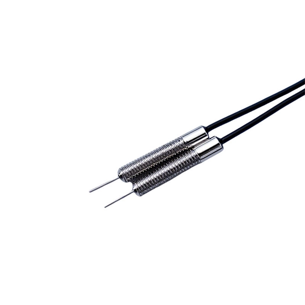
Product Features: Square protective box, suitable for skin cable and leather cable tight protection 6cm in length of skin heat shrink tube welding protection. A close connection between the leather cable and pigtail. Looking for specific info?. *In the era of high bandwidth, reliable fiber optic power equipment is particularly important. This handheld photometer can help check cable performance, calculate relative power loss, locate faults, and troubleshoot. *Measure the length of network cables, coaxial cables, and telephone cables. Able. Usually ships within 3 to 4 weeks Click here for details of availability. Able to test open, short, cross-connect, See more product details TABKER 4000667180167 3 x 2 x 1. Check each product page for other buying options. Price and other details may vary based on product size and color. Need help?. power across any given fiber. This document will serve as an overview of the major features and functions of the device and will ofer tips for trouble shooting com on issues in optical networks. If you are looking for a low cost device capable of saving and reporting take a look at the RP460 or. ments to the instrument's performance and functionality. The figures given in this manual ion of this manual to ensure the accuracy of its contents. However, should you have any questions or fi gistered users with a variety of information and services. Please allow us to serve you best by.
[PDF]

Learn how to monitor SFP optical power on Cisco switches, interpret Tx/Rx levels, and troubleshoot fiber link issues. Step-by-step CLI commands, model-specific guidance, and best practices included. In this article, we will break down the key factors influencing TX/RX power, explain how to calculate the optical power budget, and provide actionable insights for optimizing your network's performance using SFP modules. SFP (Small Form-Factor Pluggable) modules are compact transceivers that allow. SFP (Small Form-factor Pluggable) optical modules are compact, hot-pluggable transceivers that enable network equipment to connect seamlessly to fiber and copper links. Even if an interface appears up, degraded Tx/Rx levels can cause intermittent flapping, packet loss, or err-disabled states. Think of it as the “translator” for your network equipment, converting electrical signals into optical signals. The most two important factors of the SFP transceiver: Output power (TX power) and receiver sensitivity (RX sensitivity). The optical TX power is the signal level leaving from that device, which should be within the transmitter power range. The RX sensitivity is the incoming signal level being. In current network communication, SFP optical modules are an indispensable physical foundation for building network channels. They form high-speed channels for optical signal transmission. Therefore, to ensure their.
[PDF]

An optical module's actual transmit power measured by an optical power meter is lower than the nominal transmit power of the power module. The possible causes are: Bores of the optical module are contaminated. Stable optical power is the foundation of every high-capacity optical transport system. Even minor deviations—whether too high, too low, or unstable—can impact signal integrity, trigger service alarms, or interrupt traffic on DWDM, OTN, or long-haul optical line systems. This is the domain of Cell-to-Module (CTM) power loss, a series of. This paper reviews methods for reducing different optical and electrical loss mechanisms in PV modules and for increasing the optical gains in order to achieve higher CTM ratios. Various solutions for optimizing PV modules by means of simulations and experimental prototypes are recommended. Have you ever experienced an unexpected network outage due to the failure of an SFP/SFP+ optical transceiver? Network outages can bring your ability to communicate and work to a halt, and your IT team will likely be frantically looking for a solution. It is important to understand how to. This article provides an in-depth analysis of two key performance indicators of optical modules: transmitter power and receiver sensitivity. Transmitter power characterizes the average optical power output from the laser under rated conditions, while receiver sensitivity indicates the minimum.
[PDF]

Key finding: This paper develops analytical models and design procedures of ultra-wideband Wilkinson power dividers using linearly tapered transmission lines (TTLs) which provide size reduction and broadband performance. Read more. Power dividers are the passive electronic equipment used for splitting the power. They are now being employed in a variety of communications applications such as telephonic, antennas configurations, mobile connectivity, internet technology, & optics, etc. They come up with very low loss, operate at. RF and microwave power splitters and dividers create two copies of the same signal, while ideally preventing crosstalk between the outputs. Doing this with minimal loss while maintaining signal integrity is a challenge. In this article we explain how power splitters work and what the tradeoffs are. The rise of wireless connectivity requirements for applications such as Internet of Things (IoT), cellular, and automotive electronics is resulting in systems that are increasingly using RF signals, components, and subsystems. Often, designers need to direct these signals to more than a single. A power divider is a passive electronic device used in radio frequency (RF) and microwave applications to split an input signal into multiple output signals with equal or specified power levels, while maintaining impedance matching to minimize signal reflection and loss. How can power dividers.
[PDF]
Find Angola Cable manufacturers & suppliers with shipment details on Trademo. Access global exporters database and gain exporter insights. Angola Cables is an Angolan telecommunications multinational operating in the wholesale market. It sells international transmission capacity through submarine fiber optic cables and IP Transit and manages IXP Angonix in Luanda, Angola and the AngoNAP data center in Fortaleza, Brazil (Tier 3). Subscribe to global trade data intelligence to discover new business. As per Volza's Angola Import data, Optical fibre cable import shipments in Angola stood at 546, imported by 14 Angola Importers from 13 Suppliers. Angola imports most of its Optical fibre cable from Portugal, Netherlands and Brazil. The top 3 importers of Optical fibre cable are Brazil with 30,410. Contact us to understand how D&B calculated your company's specific ESG Ranking, provide new or updated information to ensure your company's ESG Ranking remains accurate and up to date, or dispute your current ranking. Unlock full sales materials and reports Dynamic search and list-building. Angola Cables is the leading South Atlantic submarine fiber optic cable system developer owner and wholesale operator. Over the period under review, the total consumption indicated a measured expansion from 2012 to 2025: its value increased at an average annual rate of X% over the last twelve years.
[PDF]
Whether you're installing new fiber optic cables or troubleshooting and repairing an existing fiber network, a working knowledge of the regulations that apply to your project can help you (and your team) stay s.
[PDF]
Optical isolators utilize retarders to prevent unwanted reflections, while optical attenuators adjust light intensity by varying polarization alignment. Polarization rotators and variable beam splitters allow controlled redirection of light for applications in optical. There are two primary types of attenuators—variable and fixed. Variable optical attenuators (VOAs) allow for manually adjusting the attenuation of the signal, which is ideal when there is a need to precisely balance signals strength. This is typically achieved by adjusting a screw that changes the. Beamsplitters are optical components used to split incident light at a designated ratio into two separate beams. Additionally, beamsplitters can be used in reverse to combine two different beams into a single one. Beamsplitters are often classified according to their construction: cube or plate. A beam splitter or beamsplitter is an optical device that splits a beam of light into a transmitted and a reflected beam. It is a crucial part of many optical experimental and measurement systems, such as interferometers, also finding widespread application in fibre optic telecommunications. a laser beam) into two (or sometimes more) beams, which may or may not have the same optical power (radiant flux). They are used to divide a beam of light into two or more separate beams. Depending on the design, beam splitters can either reflect a portion of the incoming light and transmit the.
[PDF]

Optical Modules are hot swappable, and you do not need to power off the device when replacing Optical Modules. Optical Modules are electrostatic-sensitive components. In most enterprise networking environments, the ability to replace hardware without shutting down equipment is essential for maintaining uptime. Do not insert an optical module reversely. Gently pull the module latch or release ring, depending on the module design. Remove the module in a straight motion – do not twist or pull at an angle. Reapply the. Before you begin removing a transceiver from the router, ensure that you have taken the necessary precautions for safe handling of lasers (see Laser and LED Safety Guidelines and Warnings). Ensure that you have the following parts and tools available: The transceivers for the router are. An optical module implements optical-electrical conversion, enabling optical transmission between a DRH and other devices. Disconnecting the optical fibers interrupts the transmission of CPRI signals.
[PDF]
