
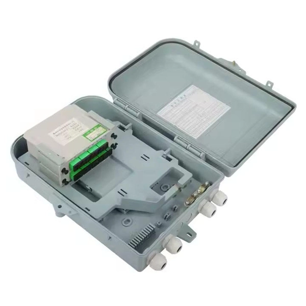
In modern FTTH architectures, the ODN is the physical fiber layer that distributes optical signals from the central office to end users. Operators consider ODN design as one of the most important factors affecting: Network coverage Optical loss performance Deployment cost. This passive layer is known as the Optical Distribution Network (ODN). Its role is to provide an optical transmission channel between the OLT and the ONU. The ODN network design is a physical facility that connects the communication room and user equipment, and is a key component. Short summary: The Optical Distribution Network (ODN) is the passive infrastructure linking the central office to the subscriber in FTTH. This guide delves into essential ODN components like splitters, distribution boxes, and ODFs, showcasing how Hainan ZTO Cable Co. It's the silent, robust highway that delivers blazing-fast Fiber-to-the-Home (FTTH) and 5G services. The maximum permissible optical power attenuation between OLT optical ports to ONT input is 28dB, which is by utilizing the so-called Class B optical network. At the heart of every Fiber-to-the-Home (FTTH) deployment lies the Optical Distribution Network (ODN) — a meticulously engineered passive infrastructure that enables operators to deliver massive bandwidth, low latency, and reliable service to millions of users. The ODN connects the Optical Line.
[PDF]
Click Systems tab Electrical panel Cable Tray. From the Type Selector, select the cable tray type, with or without fittings. On the Options Bar, specify the width, height, offset, or bend radius. more. I am preparing Cable Tray Drawing where i need to provide Cable tray tags on each tray. for that I have Modified default tray Tag family as per my requirement. I use “Comment” Parameter to to tag my cable trays. in my Model there are many Trays and it is very much lengthy and time consuming task. Understand how to model a cable tray using the systems tab in the electrical section for effective coordination, especially in the electrical room. Learn how to set the middle elevation, draw through the room, avoid conflicting elements, and create a detailed and clear visualization of the cable. Sized for the cable fill of the runs it carries. Above lights, below ducts — coordinate with ceiling plenum. Tees, crosses, and reducers handle every direction change. Noble Desktop's Revit MEP Certification Course covers Revit fundamentals — a strong foundation before specializing in mechanical. Join this channel to get access to perks: This lesson walks through how to start a project and properly set up for Electrical Cable Tray design in Revit 2025. It focuses on template selection, component availability, and basic setup steps. Start With the Right Template Opens a new project and.
[PDF]

The fastest way to test a fluorescent tube is with a multimeter set to continuity mode. Each end of the tube has two pins connected by a thin filament inside the glass. If either filament is broken, the tube is dead. The whole test takes about 30 seconds per tube once you know what. This is a complete guide for testing a fluorescent light bulb with a multimeter. You don't have to be an expert in electrical work. This process measures electrical resistance to determine if the tube has suffered an internal failure before replacing the bulb or investigating the ballast. This guide provides a comprehensive understanding of the process, equipping you with the knowledge and. To test a fluorescent light bulb, observe any of the following: flickering light, low brightness, buzzing sound, delayed start, and fading color and light variation. Turn off the power to the circuit that powers the fixture and keep the leads steady to ensure accurate readings. Multimeters provide. How to Test Light Bulbs & Fluorescent Tubes with a Multimeter (Continuity Check) Is your lamp or fixture failing to light up? Before you buy a new bulb, you need to confirm if the bulb or tube itself is the problem! A simple continuity check using a multimeter can instantly tell you if the filament.
[PDF]
We calculate cable tray weight using the formula: Volume × Material Density. The calculation accounts for side rails, rungs, and cross-bars. Find the volume of the cable tray: This depends on the dimensions (width, height, thickness) and length of the tray. Multiply the volume by the material density: This gives you the total weight. Now, let's look at the specifics of Cable Tray Weight Calculation for each tray type. 00 for bare tray weight. Used only when cover is selected. Used to estimate joints/couplers. Set to zero if unknown. Typical 200–300 mm spacing. rung bar. The calculation of cable tray weight relies on the following formula: Weight (kg) = Material Density (kg/m³) × Total Volume (m³) To apply this formula, you need: Material type profoundly influences tray weight and suitability. Below is a reference for common materials and their densities, crucial. Height of the Cable Tray You Have: mm Weight Capacity of the Cable Tray You Have: kg/m RESULTS Total dia of all cables: 0. 00kg/m Width of all cables: 0. 00mm YOUR SELECTION ANALYSIS WIDTH CHECK: HEIGHT CHECK: WEIGHT CHECK: REMAINING CABLE. When installing a cable tray, it is vital to make sure that the correct weight capacity of the tray is determined. Calculating the weight of a cable tray is not always.
[PDF]

In this article, we'll provide step-by-step instructions on how to install a round junction box in a wall, as well as tips on safety and proper wiring techniques. First, you need to determine the. A junction box provides a code-approved place to house wire connections, whether for outlets, switches, or splices. Here's how to install one. We may be compensated if you purchase through links on our website. It acts as a central connection point for various electrical wires, allowing for the easy distribution of electricity to different fixtures and devices. A properly installed and wired junction box ensures the safety and. Nothing is more dangerous and aggravating than loose wires in a junction box. In this video you'll learn how to wire junction boxes correctly. You'll also see our favorite tools to complete this task. Thanks for watching and Have A Great Day. more. Learn how to install a junction box safely, from choosing the right box and mounting it correctly to making secure splices and following basic code-safe practices. This metal or plastic housing contains wire connections, protecting them from environmental factors and physical damage. Junction boxes are fundamental in residential and.
[PDF]

This blog explains how to use Kubernetes resource quotas for efficient resource management. It covers key concepts, step-by-step implementation, YAML examples for Pods, PVCs, ConfigMaps, and tips for monitoring, troubleshooting, and optimizing quotas. On the Quota Management node of the File Server Resource Manager Microsoft ® Management Console (MMC) snap-in, you can perform the following tasks: Create quotas to limit the space allowed for a volume or folder, and generate notifications when the quota limits are approached or exceeded. Generate. Service Quotas is a service for viewing and managing your quotas easily and at scale as your AWS workloads grow. Quotas, also referred to as limits, are the maximum number of resources that you can create in an AWS account. What Are Resource Quotas in. Resource quotas are a tool for administrators to address this concern. A resource quota, defined by a ResourceQuota object, provides constraints that limit aggregate resource consumption per namespace. A ResourceQuota can also limit the quantity of objects that can be created in a namespace by API. Disk quotas allow Windows administrators to control and limit the amount of disk space that users use on the file systems of servers and workstations. Windows Server supports two types of disk quotas: File Server Resource Manager quotas and NTFS quotas.
[PDF]

In this blog, we will explore the step-by-step process of using a beamsplitter cube effectively, along with some common applications that benefit from this powerful optical tool. Step-by-Step Guide on Using a Beamsplitter Cube. A beam splitter is an optical device that divides an incoming light beam into two separate beams. One beam is typically reflected while the other is transmitted. The ratio of reflected to transmitted light can vary based on the design of the beam splitter. Beam splitters typically come in the form of a reflective device that can split beams into exactly 50/50, half of the beam being transmitted through the splitter and half being reflected. It is a crucial part of many optical experimental and measurement systems, such as interferometers, also finding widespread application in fibre optic telecommunications. Sometimes it is referred to as a half-silvered mirror. Either way, it is a simple material that YOU could use right at home for cool DIY projects like. The beam splitter has played numerous roles in many aspects of optics. For example, in quantum information the beam splitter plays essential roles in teleportation, bell measure-ments, entanglement and in fundamental studies of the photon. Additionally, beamsplitters can be used in reverse to combine two different beams into a single one. Beamsplitters are often classified according to their construction: cube or plate.
[PDF]
Den här guiden går igenom allt du behöver känna till när du vill koppla din egen router till fiber, vilka alternativ som finns, vilka inställningar som krävs och hur du felsöker om något inte fungerar som det ska. However, setting up a fiber optic connection to your router can seem daunting if you're unfamiliar with the process. In this guide, we'll walk you through how to connect a fiber optic cable to a router safely and efficiently. Why Use Fiber Optic Internet? Before diving into the setup, let's quickly. Setting up a fiber internet connection requires understanding key hardware components and following a specific connection sequence to establish your home network. This comprehensive guide combines industry standards with field-tested practices to ensure you achieve a rock-solid.
[PDF]

In the 2020 NEC ®, no more than 18 inches of cable length is allowed between the cable entry to the box and the closest cable support (see image). Below is a preview of the NEC®. ORG for the complete code section. The previous code language could technically allow an unlimited length of coiled up NM cable inside the wall as long as it was secured within 12 inches of the box. This code is based upon the type of box, wires, wire sizes, wire clamps and conduit fittings. Adjustments are made for the ground wire as you will see in the. Calculate and select the right number and spacing of cables for junction boxes using NEC guidelines to ensure safe, code-compliant electrical installations. This step keeps your project safe and. According to the National Electrical Code (NEC), the conductor must be long enough to extend outside the box's opening. This length allows enough room to connect, splice, or terminate wires without strain or damage. If wires are too short, they may fail inspection or create hazards during. The length of wire left inside an electrical box is a matter of strict compliance, safety, and functionality. Having the correct amount of slack ensures that future maintenance, repairs, or device replacements can be performed without difficulty. Proper electrical box fill calculations are critical for code compliance and safety in both residential and commercial installations.
[PDF]

Professional Cable Tray Elbow Making | Metal Fabrication Tutorial Learn how to make cable tray elbows professionally with step-by-step guidance. This video shows metal fabrication techniques, DIY cable tray projects, and tips for perfect bends and joints. Whether you are a DIY enthusiast. The method for producing bridge bend elbows is as follows: Take a 90-degree cable tray bend elbow as an example, and apply the same principles for 45-degree bends accordingly. The length of the bottom side (bottom diagonal) after bending the cable tray should be equal to the width of the cable. This manual is designed to guide workers through the detailed production process of ladder cable trays, including the manufacture of horizontal elbows, tees, crosses, reducing bends, and vertical bends, with emphasis on precision, safety, and quality control. What's Involved in Producing Ladder. The bends, tees, crosses, risers and reducers of wire mesh cable tray can be easily and quickly made live at the project by using a bolt cutter. Since the jaws of the bolt cutter drags a layer of zinc across the cut end and forms a protective layer. When a wire cable tray is cut, the fact that a. How to bend 22. 5 DEGREE OF CABLE TRAY 3 LA. How to bend 90 degree of cable tray 3 line with the same distance :// • HOW TO BEND 90 DEGREE OF CABLE TRAY 3 LINE. Enjoy the videos and music you love, upload original content, and share it all with friends, family, and the world on YouTube.
[PDF]
This guide dives deep into the most prevalent fiber optic network problems, their root causes, and actionable solutions. Fiber optic technology is essential for modern communication, offering unparalleled speed, reliability, and efficiency. However, improper installation can lead to severe performance issues, expensive repairs, and unnecessary downtime. To ensure a high-functioning fiber optic network, avoid these. Understanding the common causes of failure and implementing preventive measures is essential to maintaining reliable networks and avoiding costly downtime. In this article, we explore the primary modes of field failure in fiber optic cables and outline best practices to prevent them. This article outlines three key errors and how to avoid them.
[PDF]

Average Optical Power: How bright the light is (measured in dBm). Too dim? Your signal gets lost in the fiber. Extinction Ratio: The difference between “on” (1) and “off” (0) light power. A higher ratio = cleaner signals. Transmitter Side: An electrical signal hits a laser diode (LD) or LED, which spits out light. Receiver Side: Light enters a photodetector (like a tiny solar cell), which turns it back into electricity. A built-in amplifier boosts the signal for your. The average transmitted optical power refers to the optical power output by the light source at the transmitting end of the optical module under normal working conditions, which can be understood as the intensity of light. In communication, we usually use dBm to represent optical power. However, in practical use, we adopt the average Tx power. The transmission power is related to the. This article provides an in-depth analysis of two key performance indicators of optical modules: transmitter power and receiver sensitivity. Transmitter power characterizes the average optical power output from the laser under rated conditions, while receiver sensitivity indicates the minimum. An optical module is a connecting module that serves as an optical-electrical conversion device. At the receiver end, the optical signals are reconverted into electrical.
[PDF]

In this video, we'll show you how to connect an energy meter to a distribution board (DB) safely and efficiently. energy meter connection with distribution box How to Connect an Energy Meter to Your Distribution Box Easily Steps to Properly Connect Your Energy Meter to a Distribution Box. It plays a vital role in ensuring the safe and efficient distribution of electricity throughout the premises. What is the wire from the meter to the breaker box? Also. Always begin with disconnecting the main supply before accessing any enclosure containing distribution components. This prevents arc faults and ensures safety when modifying or inspecting current paths. This “meter to panel” wiring establishes the pathway for all incoming electrical power from the grid to the home. Its primary function is to safely and reliably. Distribution Board aslo know as “Panel Board”, “Switch & Fuse Board” or “Consumer Unit” is a box installed in the building containing on protective devices, such as circuit breaker, fuses, isolator, switches, RCDs and MCBs etc. The electric main supply (230V AC & 120V AC in US) is connected through. Changed Texas's reference diagram for the 3 wire network 120/208 Volt single phase self-contained Revised Figures 13, 14, 14b. Limited the meter location from pad mount transformer for PSO. Removed unistrut being listed as an alternative means for mounting the meter box. APCo and TX do not allow.
[PDF]

The first thing you should do is locate the fiber optic cable that comes from the service provider. Once inserted, make sure it is. However, setting up a fiber optic connection to your router can seem daunting if you're unfamiliar with the process. This comprehensive guide combines industry standards with field-tested practices to ensure you achieve a rock-solid. Setting up a fiber internet connection requires understanding key hardware components and following a specific connection sequence to establish your home network. This guide details the necessary physical and digital steps to connect your fiber line and activate your internet service. The technician powers, tests, and activates the connection to confirm full speed and signal quality. * In some instances, the ONT and the router are all in the same device, generally called a combo unit. Here's a step-by-step guide to help you through it. Understand the Basics Before diving in, familiarize yourself with the components involved:. Tecnobits - Router - How to connect a fiber optic cable to the router Hello, Tecnobits! 👋 Connecting fiber optic cables to the router so that your internet flies like a spaceship! 😉 Explore with us on our website! And don't miss our latest news. See you soon! 🚀 How to connect a fiber optic.
[PDF]

Fiber Optic Welding How To Joint Fiber Optic Cablesplicing fiber optic cable,fiber optic splice,fiber optic,fiber optics,fiber splice,how to splice,fibre opt. The optical fiber connection adopts the fusion splicing method. The whole process is similar to the welding of metal wires, and it is generally carried out by electric isolation. At the moment, there are two methods of connection: Thermal welding of optical fibers consists in bringing the ends of the conductor to melting using a fiber optic splicer, and more specifically - located inside the electrodes. The welded ends are then pressed and a weld is formed. The most work is waiting for installers, whose tasks can be divided into several stages: In this part, we will deal with the second stage, i. welding, which is considered to be one of the most difficult parts of installers' work in. Open the stripping tube and wipe the grease on the optical fiber with toilet paper and alcohol cotton. On the welding disc, make the optical fiber precoil first and cut the optical fiber into an appropriate length to facilitate the coil fiber work after welding. Add heat shrink tube. Procedure. Another method is to use the so-called mechanical welding. It uses special parts that are prepared in advance to connect the two ends. Thanks to this, you can connect two ends of the cable with a ready-made splice, without the need to use an optical fiber splicer. While this method may appear to be.
[PDF]

