
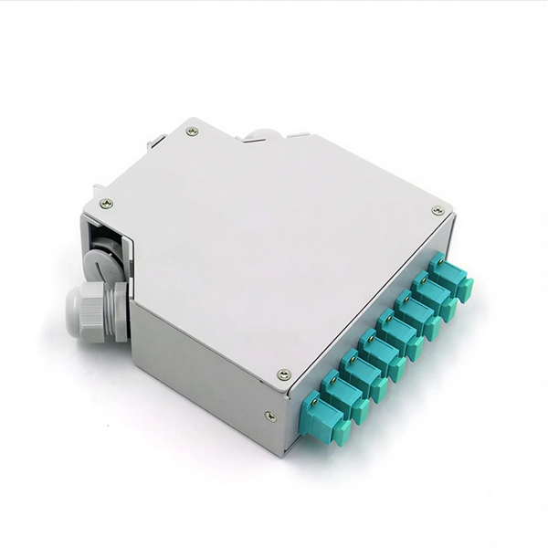
In modern FTTH architectures, the ODN is the physical fiber layer that distributes optical signals from the central office to end users. Operators consider ODN design as one of the most important factors affecting: Network coverage Optical loss performance Deployment cost. This passive layer is known as the Optical Distribution Network (ODN). Its role is to provide an optical transmission channel between the OLT and the ONU. The ODN network design is a physical facility that connects the communication room and user equipment, and is a key component. Short summary: The Optical Distribution Network (ODN) is the passive infrastructure linking the central office to the subscriber in FTTH. This guide delves into essential ODN components like splitters, distribution boxes, and ODFs, showcasing how Hainan ZTO Cable Co. It's the silent, robust highway that delivers blazing-fast Fiber-to-the-Home (FTTH) and 5G services. The maximum permissible optical power attenuation between OLT optical ports to ONT input is 28dB, which is by utilizing the so-called Class B optical network. At the heart of every Fiber-to-the-Home (FTTH) deployment lies the Optical Distribution Network (ODN) — a meticulously engineered passive infrastructure that enables operators to deliver massive bandwidth, low latency, and reliable service to millions of users. The ODN connects the Optical Line.
[PDF]

However, essentially, optical fiber patch cords are more like "finished connection lines", while optical fiber pigtails are "semi-finished connectors". The difference in this core positioning determines the vast disparity between them in structure, connection methods. Executive Summary: A fiber optic pigtail is one of the most commonly specified yet least understood components in structured cabling. Get the wrong connector type, the wrong polish, or skip proper fusion splicing technique—and you're looking at elevated signal loss, increased back reflection, and a. When you build or upgrade a fiber network, the same four words pop up everywhere— fiber optic (bare fiber), pigtail, patch cord, optical cable. They're related, but they are not interchangeable. Mixing them up drives costs higher, increases loss, and slows your rollout. The good news? Once you nail. A fiber pigtail is typically a fiber optic cable with one end factory pre-terminated fiber connector and the other exposed fiber. It is usually suitable for field termination using a mechanical or fusion splicer. The connector end plugs into devices like transceivers or patch panels, while the bare end is typically fusion spliced to a fiber optic cable. This setup ensures. As outlined in T13: Fiber Optic Fundamentals, an optical fiber is a coaxial cylindrical dielectric waveguide with a core refractive index exceeding that of its cladding.
[PDF]

Fiber optic cables use total internal reflection to keep light signals bouncing within the core, allowing data to travel quickly and with minimal loss. An optical fiber is comprised of a light-carrying core in the center, surrounded by a cladding that acts to traps light in the. Optical fibers are thin glass rods that use the properties of light reflection and refraction to transmit data over long distances. They actively shuttle data encoded in pulsing light across vast distances using only subtle differences in materials. They consist of three elements as shown in Figure 1: a central core, cladding and a protective coating. Optical fibers operate on the principle of total internal reflection, which. Refraction and total internal reflection (TIR) are the two fundamental optical principles that allow light to propagate through optical fibers over long distances with minimal loss. Understanding these mechanisms is essential for designing, installing, and troubleshooting fiber networks in FTTH. Fiber optic cables use a similar concept to guide light. Fiber optic. Describe the workings and uses of fiber optics. Analyze the reason for the sparkle of diamonds. A good-quality mirror may reflect more than 90% of the light that falls on it, absorbing the rest.
[PDF]
Mid-Range — 2,000 ft outdoor run with conduit and 4 terminations: Cable $0. 60/ft, Permits $350, Delivery $120, Accessories $250. Total ≈ $4,940–$6,120. Multi-fiber cables worked as described and with no issues. Buy 4 Fibers OM3 Multimode PVC (OFNR) Indoor Tight Buffered Multifiber Pre-Terminated Cable at reliable fiber optic cable supplier, best price & Fast shipping. Typical rates range from $0. 00 per ft depending on terrain, access, and required precision for termination. Commercial building installations with 100-200 network drops generally range from $15,000 to $30,000. Single-mode fiber costs less per foot than multimode fiber, but it requires more. Aluminum Folding Telescopic Ladder 4. 4m for Home & Outdoor ₹ 6,550. 00 Original price was: ₹6,550. 4 Core FTTH Single Mode Optical Fiber Cable – Round OD 5. High quality fiber optic cables from Corning, AFL, OCC, Mohawk and other leading manufacturers. Aerial, ADSS, armored, distribution, direct burial and more. Pricing (USD) Filter the results in the table by unit price based on your quantity. A tariff of 8% may be applied if shipping to the United States.
[PDF]

Fiber optic network design (896. 83 KB). I'm needing symbols for common fiber optic components, cables, connectors, backbone ports, etc. Can anyone help me out? Some examples of a diagram would also help. 10-27-2018 01:41 AM Do you know if there's some symbol standard fir this kind of schematics? I surely don't know. If you can be helpful. Free CAD and BIM blocks library - content for AutoCAD, AutoCAD LT, Revit, Inventor, Fusion 360 and other 2D and 3D CAD applications by Autodesk. CAD blocks and files can be downloaded in the formats DWG, RFA, IPT, F3D. You can exchange useful blocks and symbols with other CAD and BIM users. See. Search by part number or description such as CAT5, CAT6, OSP, etc. Sort by any of the table headers. Use the drop down menu to filter by product category and type. Sort by any. Welcome to the Corning LANscape® Solutions Product Drawings Resource Center, your complete source for our optical hardware component drawings. The two-dimensional and isometric hardware products drawings are available in PDF (Adobe® Acrobat®), DXF (AutoCAD®), VSS (Visio® Stencil) formats, and. Be among the first to receive important product updates, insights and news. Of all these options, the most favored one is optical cables because they offer uninterrupted swift data transmission.
[PDF]

Fiber optic cables offer superior performance compared to copper cables, especially over long distances. They provide higher data transmission rates, larger bandwidths and are immune to electromagnetic interference. Fiber optic cables and copper wires are the two primary types of cables used in networks. Fiber optic cables transmit data using light waves, enabling higher. Fiber optic tends to be the more premium solution, while copper wiring is far more common, but why is that? What are the differences between these two cable types, and why might you want to pick one over the other? Here's everything you need to know about fiber vs. Copper wire is more susceptible to interference and has limited data capacity, making optical fiber the preferred choice for modern high-speed. If you're deciding between copper and fiber optic cables, it's not just a question of cost, it's about purpose, environment, and future readiness. Both have distinct strengths that can serve very different networking needs depending on your setup. Fiber optic cables provide. In today's fast-paced digital world, choosing the right network cable can significantly impact the performance, reliability, and security of your communications infrastructure. Among the most commonly used cables are copper and fiber optic cables, each offering unique advantages depending on the.
[PDF]

Step-by-step instructions on how to install fiber optic connectors like LC, SC, and ST. Includes tool recommendations, epoxy and polish method, and safety tips for installers and technicians. Even with sharing in efficiency, fiber connector installation is still an effort in which precision and safety form the central themes. A correct installation creates a low-loss, reliable connection essential for high-speed data transmission. While fiber optics enable speeds and distances copper can't match, the system's performance hinges. Next, we will introduce in detail the installation of several different types of fiber optic connectors. How To Connect Fiber Optic Cable To Connector? The connection methods for SC, FC, ST, and FT connectors with optical fibers are basically the same. Unlike foil strain gauges, fiber is often suitable for embedment. Sensuron's FOS offers hundreds to thousands of sensing points with a resolution of 1. 4 mm along a single sensing fiber. This video demonstrates the process of installing a fiber optic sensor to a substrate for measuring distributed mechanical strain. Fiber optic connectors are devices that join two fiber optic cables together, allowing the transmission of light signals with minimal loss. They come in various types, such as SC, LC, ST.
[PDF]

An SC/APC fiber optic adapter is a passive mechanical interface used to join two SC connectors that have angled physical contact (APC) ferrules, typically polished at 8°. Fiber couplers belong to the basic components of many fiber-optic setups. Note that the term fiber coupler is used with two different meanings: It can be an optical fiber device with one or more input fibers and one or more output fibers. It covers a wide range of fiber optic devices such as optical splitters, optical combiners, and optical couplers. A fiber optic coupler is a device that can distribute the optical signal. This small, inexpensive component is critical for aligning and mating two SC/APC connectors while preserving low insertion loss and ultra‑high return loss performance. Its core function is to distribute (split) or combine (combine) optical power while maintaining the spectral composition of the signal. The device allows the transmission of light waves through multiple paths. It functions by dividing a single incoming light path into multiple outgoing paths, or by combining light from several input paths into a single output fiber. This capability is fundamental.
[PDF]

Fiber optic loss calculation formula: Total link loss (LL) = Cable attenuation + Connector attenuation + Fusion attenuation [Note: If there are other components (such as attenuators), their attenuation values can be added]. Intrinsic Optical Fiber Losses comprise of absorption loss, dispersion loss and scattering loss caused by the structural defects. The detailed information about these optical losses and how to reduce them are. Calculate fiber optic signal loss based on cable length, attenuation, and connector losses. Determine cable loss, connector loss, and total system loss in decibels (dB) to assess signal quality and repeater requirements. Fiber optic loss is calculated in two parts: cable loss and connector loss. This calculator determines fiber loss based on input power, output power, and the length of the fiber optic cable. In summary, fiber optic loss is. Use this worksheet to input values for all variables that will impact your system's performance. After entering your values, please ensure you click the 'Calculate Link Loss' button at the bottom of the page to generate your total link loss. This step is necessary to see if your system falls within. Optical fiber loss is a term for signal loss affecting transmission reliability. Optical fiber loss is.
[PDF]

A fiber optic cable is a high-speed data transmission medium that carries information as light pulses through strands of glass or plastic fibers. Each strand contains a core and cladding that use total internal reflection to guide the light signal across long distances with minimal. What Does a Fiber Optic Cable Look Like? Fiber optic cables are often seen as the gold standard for network cabling. Unlike copper wires, which are limited by lower data transmission speeds, shorter transmission distances, and higher susceptibility to electromagnetic interference, fiber optic. A TOSLINK optical fiber cable with a clear jacket. These cables are used mainly for digital audio connections between devices. A fiber-optic cable, also known as an optical-fiber cable, is an assembly similar to an electrical cable but containing one or more optical fibers that are used to carry. A fiber optic cable is a data-transmission medium that uses light signals instead of electricity to transfer information. It consists of glass or plastic fibers surrounded by cladding, buffer, and protective layers. In the 1960s, modern optical fiber was created. This fundamental difference is why it's so fast and efficient. The process relies on a principle called Total Internal Reflection. Unlike copper cables, which depend on electrical signals, fiber.
[PDF]
The communication system of fiber optics is well understood by studying the parts and sections of it. The major elements of an optical fiber communication system are shown in the following figure. The ba.
[PDF]

Optical Fiber Communication (OFC) revolutionizes modern telecommunications, enabling rapid data transfer across long distances with minimal signal loss. This comprehensive review explores OFC's historical evolution, core principles, components, and versatile applications. It traces OFC's. Additionally, optical fiber is lightweight and less susceptible to noise (no electromagnetic induction). Optical fiber consists of a cylindrical core that propagates light and a concentric cladding that surrounds it. The cladding's refractive index is slightly smaller than that of the core, which. Fibre optics and optical communications is the use of thin strands of glass for sending information encoded into light over long distances. Total internal reflection prevents light inserted into one end of the fibre from escaping through the sides. Keywords: Optical fibers, communication systems, data. Figure 1: Illustration of the inverse-square law of light intensity – the light's intensity diminishes with the square of the distance, which free-space optical signals must overcome (leading to very weak reception at long range) Figure 1 illustrates how light intensity decreases as distance.
[PDF]

This article provides a detailed technical comparison between fiber optic and copper cables, offering a clear perspective for engineers, network architects, and procurement managers. The core distinction between the two technologies lies in the physics of data. There are significant differences in performance between ADSS cables (all-dielectric self-supporting optical cables) and traditional optical cables, which are mainly reflected in the following aspects: 1. This type of fiber optic cable is designed to support its own weight without the need for additional support structures like messenger wires. The ADSS. There are several factors to assess when deciding which cable type is right for your application, including speed of connection for new customers, ease of changes and repairs, installer certification requirements, and the ability to expand the network over time. ADSS Fiber Optic Cables are a type of optical fiber cable designed specifically for. All-dielectric self-supporting (ADSS) cable is a type of optical fiber cable that is strong enough to support itself between structures without using conductive metal elements. It is used by electrical utility companies as a communications medium, installed along existing overhead transmission.
[PDF]

A single strand of glass fiber, called single-mode fiber, is used to transmit single-mode or light beams. It can transmit higher bandwidth than multimode fiber but requires a light source with a limited spectral range. There are mainly two types of optical fibers, single-mode optical fiber, and multimode optical fiber, which differ in the way light propagates. The latter is used for short-distance transmission, while the former is typically used for long-distance signal transmission. Please refer to the article. Single fiber modules (BiDi) use one fiber for both transmitting and receiving data. This saves space and money. Dual fiber modules use two fibers. They are easier to set up and give steady communication. Single-mode optical modules are best for long distances and fast speeds. Modes are the possible solutions of the Helmholtz equation for waves, which is obtained by combining. Optical fiber transmission is based on the principle of total internal reflection, where light signals are transmitted through a thin glass or plastic fiber with a core and cladding. The core has a higher refractive index than the cladding, causing the light signal to be reflected back into the. OS1 single mode fiber optic cables are made with a single mode fiber core, which means that they have a very small core diameter of 9 microns. Each type serves distinct applications based on its light transmission characteristics. Very small core (~8–10 µm). Carries one light path (mode).
[PDF]

This practical file details experiments conducted in Optical Fiber Communication, covering modulation techniques, system components, and performance analysis. An optical fiber is a glass or plastic fiber designed to guide light along its length, widely used in fiber-optic communication, which permits transmission over longer distances and at higher data rates than other forms of communications. Fiber-optic communication is a method of transmitting. Availability of plastic optical fiber (POF) The plastic optical fiber used in some of these experiments is available for science distributors. It is a 1000micron (1mm) POF available from several suppliers. FOA has samples available at no cost for teachers at schools in the US. Key experiments include amplitude modulation, frequency modulation, and pulse width modulation, aimed at understanding fiber optic systems. This document summarizes 10 experiments on optical fiber communication: 1. Studying a 650mm fiber optic analog link and the relationship between input and received signals. Optical fiber communication Laboratory Optical fiber communication Laboratory List of Experiments: 1. To set up a analog optical fiber link 2. To measure the characteristics of LED and LASER 5. Tech curriculum designed to provide a comprehensive understanding of optical fiber communication systems. This lab offers an immersive, web-based simulator that enables you to explore and experiment with key concepts in optical.
[PDF]
