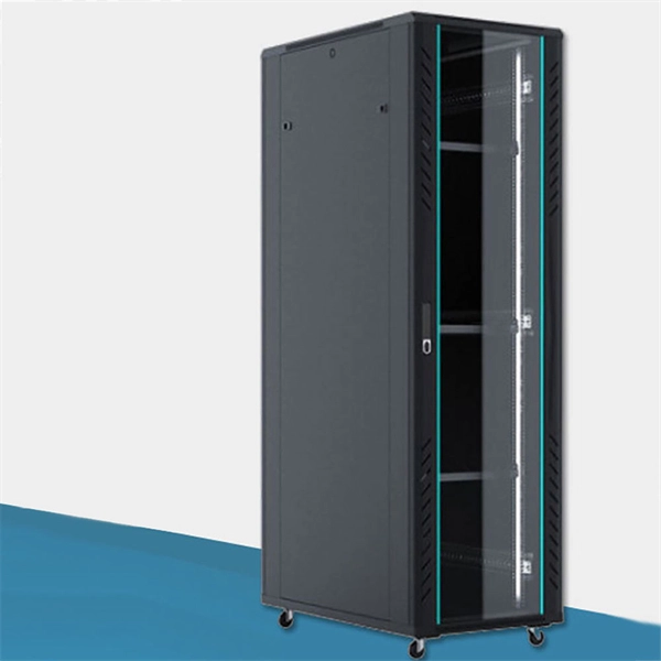
An aggregation layer usually comprises a few blocks of two switches in MCLAG. By design, it therefore provides resiliency because it will always be deployed in pairs of switches and comes with a recommendation to deploy only dual hot swappable power supplies and redundant fans in each switch to. IEEE 802. 3ad link aggregation enables you to group Ethernet interfaces to form a single link layer interface, also known as a link aggregation group (LAG) or bundle. The LAG balances. Switch-to-Switch Aggregation: This is useful in scenarios where you need to interconnect multiple switches to increase the bandwidth available between them and ensure network redundancy. It helps in managing higher traffic loads between switches. Switch-to-Client Aggregation: This is beneficial. An Aggregation or "Top-of-Rack" switch is designed to connect everything in a rack at high speeds, then have an even bigger pipe out to the rest of the network. The Pro Aggregation does this with it's SFP28 25Gbps ports. While there are many approaches, this article. Would I have any issues if I linked a Ubiquiti aggregation switch to another? We have some fiber runs in our building, but there isn't enough runs to supply all my switch locations and a couple of the runs are too long for 10gig. So, what I want to do is install an aggregate switch at the source.
[PDF]
Learn more!. Learn more!. Check our Latest Networking Switches with best features and cost efficient, Heavy on Features not on Pocket Purpose-engineered solutions for the three pillars of India's network infrastructure ecosystem. Deploy advanced switching solutions across access and aggregation layers. Built for. The product has completed the End of Life (EOL) process effective on January 1, 2026. For more details, please refer to the EOL Notice. The Edgecore AGR100 router meets the high-performance, availability, and network-scaling requirements of cloud data centers and carrier access providers. 8 Tbps high-density 100G/25G Layer 3 Etherlighting™ aggregation switch with MC-LAG support for high availability system design. Requires a 4-post rack, or a center-mount bracket or cantilever shelf on 2-post racks for optimal support. Contact your EET Sales for the needed Ubiquiti Registration. Enterprise Campus Aggregation. Designed to combine compressed and uncompressed video / audio streams as well as TCP traffic over IP, the MDX series is ideal. Individually Configure Ports for Optimum Flexibility The AA100G32AC is a purpose built network aggregator, designed for use in top-of-rack applications or at the network edge. The system can be used to optimize port utilization of existing infrastructure or as a stand alone device in L2-L4.
[PDF]
This page contains wiring diagrams for household light switches and includes: a switch loop, single-pole switches, light dimmer, and a few choices for wiring an outlet/switch combo device. Check permit requirements before beginning electrical work. How to read these diagrams. Also included are. A house switch, also known as a light switch or electrical switch, is a device that is used to control the flow of electricity to a particular circuit in a house. It is a simple device that can be found in almost every room of a house and is used to turn lights on and off. and Be Sure to Subscribe! Make sure the circuit power has been turned off, and mark the circuit breaker or fuse to indicate that work is. The following house electrical wiring diagrams will show almost all the kinds of electrical wiring connections that serve the functions you need at a variety of outlet, light, and switch boxes. For help understanding them, be sure to open the Explanation page. This panel is the central hub that distributes electricity throughout the house. It is usually located in a basement, utility room, or garage. Understanding the wiring diagram of a typical house can help you troubleshoot any electrical problems and make upgrades or repairs with confidence.
[PDF]
A 3 × 3 all-optical interconnecting switch using three quantum dot semiconductor optical amplifier assisted Mach-Zehnder interferometers (QDSOA-MZI) has been designed. It can transmit input data to any outpu.
[PDF]
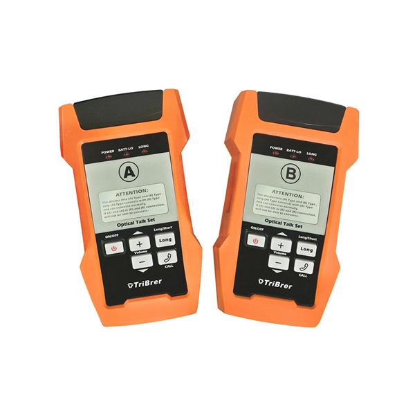
Learn how to connect your ONT, configure your router, and optimize Wi-Fi for fast, stable fiber internet at home or office. To set up your router for fiber internet quickly, connect the router to your fiber modem, access the router's settings via a web browser, and input the provided ISP credentials. Make sure to update the firmware, configure Wi-Fi security, and customize your network name for optimal performance. With. However, setting up a fiber optic connection to your router can seem daunting if you're unfamiliar with the process. In this guide, we'll walk you through how to connect a fiber optic cable to a router safely and efficiently. Why Use Fiber Optic Internet? Before diving into the setup, let's quickly. Setting up a fiber internet connection requires understanding key hardware components and following a specific connection sequence to establish your home network.
[PDF]
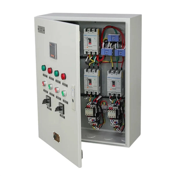
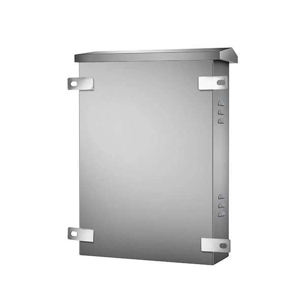
Inside the distribution box, you'll also find switches and indicators. The switches are used to control the circuits—turning them on or off as needed. A distribution box, also known as a distribution board, electrical panel, or breaker box, is an enclosure that houses electrical components responsible for distributing electricity throughout a building. It receives power from the main electrical supply and divides it into separate circuits, each. Messy distribution boxes are dangerous and very hard to fix. This guide shows you how to organize circuit breaker wiring properly. You will learn to build a safe, efficient, and professional electrical system today. Indicators, like LED lights, show the. A distribution box uses MCBs, RCDs, and busbars to protect circuits, prevent shocks, and ensure safe power distribution in homes and buildings. It acts as the central point where electricity distribution is managed inside a building. These diagrams provide a visual representation of how the electrical circuits are connected, allowing electricians and homeowners to troubleshoot issues.
[PDF]
Execute the command, display transceiver [ interface interface-type interface-number | slot-id ] [ verbose ] to check the optical module information on the device interface. When the optical module on an interface is faulty, you can run the display commands to view information about the optical module. During use, reading optical module information helps understand its real-time operating status, enabling faster troubleshooting of link abnormalities. The following uses the. See the interface module via the optical display command information, including general information of the optical module, manufacturing information, and alarm information. The specific viewing information is as follows:. Here is an example on how to query or display optical power of an interface in a Huawei Router. This is tested using NetEngine40E Universal Service Router or NE40E running version 8. Sample Output: (Can see link down and not receiving any power from the neighboring device) Or can do filtering:. Today, ETU-LINK will introduce how to query the information of optical module on Huawei switch. Next, we will introduce the query instructions of relevant parameters of optical module, and view the DDM information of interface optical modules through display command. Execute the command, display.
[PDF]
How to connect multiple switches in a network with clear steps and tips for effective setup and configuration. Switches operate at the data link layer of the OSI model, forwarding packets of data between devices based on their MAC addresses. Switches come in various shapes and sizes, ranging. Cascading switches refers to the process of connecting multiple switches together in a series, effectively expanding the network's capacity and reach. This hierarchical connection allows for efficient and seamless communication between devices, regardless of their physical location within the. In the world of networking, Ethernet switches are integral components that provide the necessary interconnects for our devices. Sometimes, one switch is not enough to meet our needs, whether in terms of port number, specific functionalities, or both. Essentially, a LAN switch sets up a series of temporary networks that span only the two devices currently exchanging data. Depending on the configuration, connecting multiple switches can also. When one switch cannot meet the number of ports and a specific functional requirement, usually users will connect multiple Ethernet switches together, so how to connect multiple Ethernet switches together during network deployment? Three common types of connections are currently available:.
[PDF]
In industrial-grade switch applications, redundant power supply (RPS) has become a critical technology for ensuring network stability. Particularly in harsh environments like photovoltaic plants and coal mining sites, power failures can lead to catastrophic consequences. This article provides. A power redundancy design means that a network device can be connected to two power sources simultaneously. In this way, if one power source fails or loses power, the other can continue supplying power to the device, ensuring uninterrupted operation. This redundancy helps maintain network. Moxa provides a wide range of industrial Ethernet switches that feature industrial-grade reliability, network redundancy, strengthened security, easy management, and competitive price-to-performance ratios. Our comprehensive portfolio includes unmanaged switches, managed switches, PoE switches. One critical factor is power stability—an unexpected power failure can disrupt an entire switch, interrupt communication, and cause costly downtime or data loss. This article explores the importance of power redundancy, how it enhances system reliability, and various methods to achieve it, particularly. Extreme Industrial Switches are a family of ruggedized Layer 2 switches designed to operate under harsh environments and extended temperature conditions. They provide continuous uptime, manageability, and operational efficiency. With flexible PoE options of IEEE 802.
[PDF]
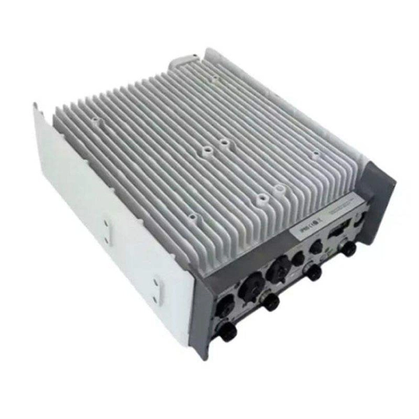
An optical line termination (OLT), also called an optical line terminal, is a device which serves as the service provider endpoint of a passive optical network. It provides two main functions: to perform conversion between the electrical signals used by the service provider's equipment and the fiber optic signals used by the passive optical network.to coordinate the multiplexing between the conversion. FeaturesOLTs include the following features: • A downstream frame processing means for receiving and churning an cell to generate a downstream frame, and converting a parallel dat. Most vendors integrate an entire fiber optic management system for ISPs to manage OLTs as well as client ONTs and as such are not interoperable. • • BT-PON.
[PDF]

Offering advanced EPON (Ethernet Passive Optical Network) technology, this ONU provides efficient data transmission, making it perfect for broadband services. With 1 Gigabit Ethernet (1Ge) ports, it supports fast internet speeds and enables seamless online experiences. ONU or Optical Network Unit is a type of optical device. Nowadays it is widely used as a media converter in internet services. The device used to convert the optical signals of the network into digital signals is called ONU. An ONU has one or more Ethernet ports that are used to connect to devices. An Optical Network Unit (ONU) is an important device in fiber optic networks, especially for FTTH (Fiber to the Home) connections. It works by connecting to the Optical Line Terminal (OLT) to deliver high-speed internet, voice, and video services directly to users. The BDCOM GP1702-1G Single Port GPON ONU is a high-performance, compact, and cost-effective optical network unit designed to bring reliable gigabit broadband connectivity to homes, offices, and small businesses. Ideal for ISPs, small towns, villages, and enterprises, this 2-port OLT delivers stable and scalable fiber internet connectivity at an affordable price.
[PDF]
Abstract: In this paper, a comprehensive study on erbium-doped fiber amplifier (EDFA) characteristics under temperature variation has been performed. The rate and propagation equations that characterize EDFA performance pumped at 980 nm and 1480 nm in the forward direction are solved numerically. The. The EDFL serials of erbium-doped fiber amplifier features a very short latency for applications which require minimum signal delay. The EDFL is built using semiconductor lasers, WDM, isolator, and erbium-doped fiber. The product has the advantages of high reliability, high power output, high gain. The world first plug and play SFP+ -EDFA, FOA is a full-functioning EDFA module with control circuitry packaged inside. It is totally compatible with conventional SFP+ optical transceiver in respect of size and pin-map. The first trans-Pacific optical cable employing EDFAs, launched in 1996, enabled stable amplification of multiple wavelength channels across thousands of kilometers without electrical regeneration. This innovation eliminated the need for thousands of electrical repeaters, significantly reducing. Erbium Doped Fibers provide the basic building blocks for fiber optic amplifiers more specifically Erbium Doped Fiber Amplifiers (EDFAs) used in broadband optical networks and CATV applications. The core of the fiber is doped with Erbium and is typically pumped with 980 or 1480 nm to produce gain.
[PDF]

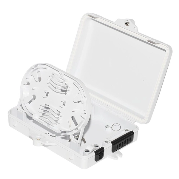
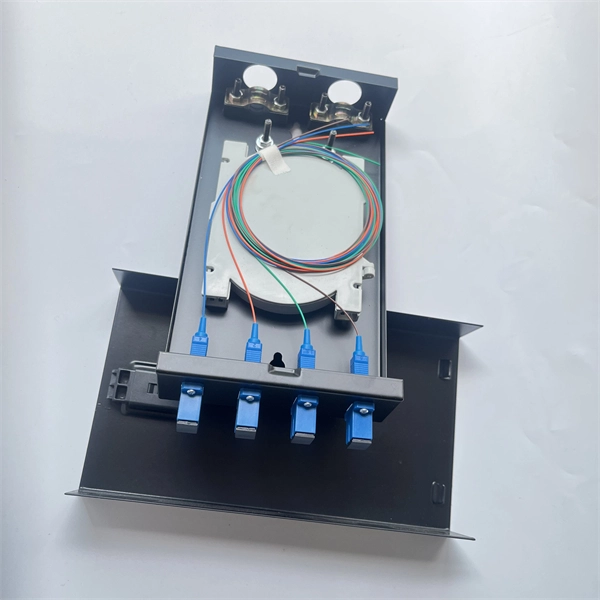
This complete guide explores everything you need to know about ODFs — from their structure, types, and key components, to installation best practices and modern design trends. Clients facing the exact demands of specialized environments—whether it's ultra-low-latency AI clusters, space-constrained military installations, or high-density telecom exchange points need more than off-the-shelf cabling. At FS, we place the customer at the heart of our operations. We are. This white paper provides a comprehensive guide to designing future-proof fiber optic networks, emphasizing a core-to-edge architectural approach. Key focus areas include backbone topologies, optical loss budgeting, standards compliance, and strategies for optimizing high-density environments like. In modern data centers and enterprise networks, Optical Distribution Frames (ODF) serve as the backbone for organizing, terminating, and managing fiber optic connections. As data centers, enterprises, telecom operators, and smart-building infrastructures deploy increasingly dense fiber links, ODFs provide the structured. Fiber optic network design refers to the specialized processes leading to a successful installation and operation of a fiber optic network. It includes first determining the type of communication system (s) which will be carried over the network, the geographic layout (premises, campus, outside.
[PDF]
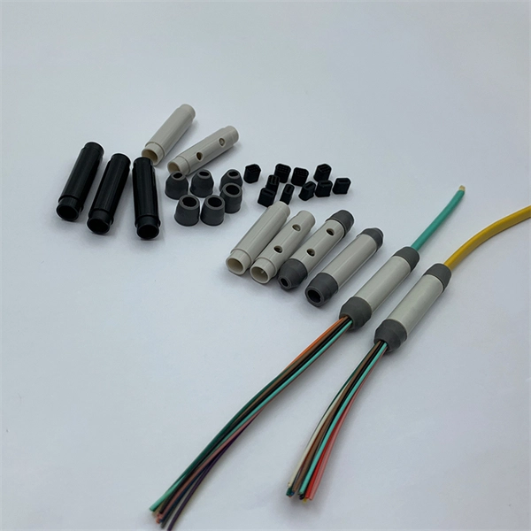
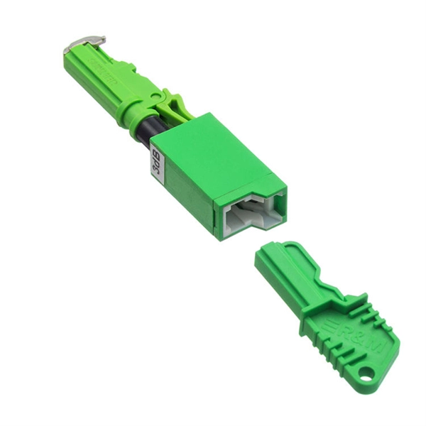
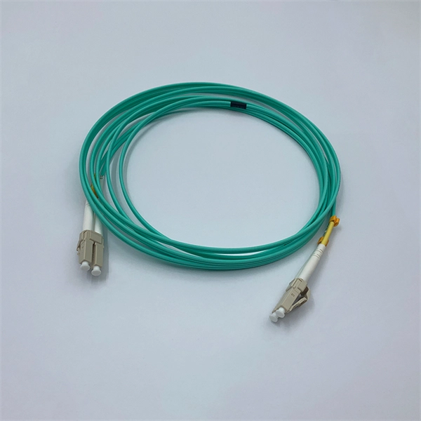
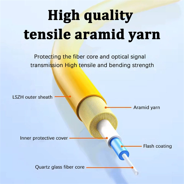
In the rapidly evolving landscape of modern networks, fiber optic connectors play a pivotal role in ensuring seamless data transmission and connectivity. These essential components bridge fibers, enabling the efficient transfer of information across various applications and. Among these components, fiber connector types are essential to network performance, reliability, and scalability. This guide will walk you through the most common fiber connector types, explaining their characteristics, advantages, and typical use cases. The connector body, which is the protective housing that holds and protects the ferrule, plays a key role in ensuring a robust and durable connection. Fiber optic connectors can. Whether it's for internet networks, telecommunications, or data centers, fiber optic cables rely heavily on connectors to establish secure and efficient connections. They link fiber optic cables, allowing data to move quickly with minimal loss. In this guide, you'll explore various types of fiber optic cable connectors, each with unique features and. Learn about the top 4 fiber optic connectors (LC, SC, ST, MTP/MPO) and find the best options for your network, optimizing performance, reliability, and data transfer in a technological age.
[PDF]
A low-voltage wiring system in buildings may be used to operate line-voltage lights, receptacles, motors, or other devices. This system is made up of low-voltage switches that operate relays that actuall.
[PDF]