In a theatre, a specialty panel known as a dimmer rack is used to feed stage lighting instruments. A U.S. style dimmer rack has a 208Y/120 volt 3-phase feed. Instead of just circuit breakers, the rack has a solid state electronic dimmer with its own circuit breaker for each stage circuit. This is known as a dimmer-per-circuit arrangement. The dimmers are equally divided across the three incomin. OverviewA distribution board (also known as panelboard, circuit breaker panel, breaker panel, electric panel, fuse box or DB box) is a component of an that divides an electrical power feed into subsidiary. North American distribution boards are generally housed in enclosures, with the positioned in two columns operable from the front. Some panelboards are provided with a door covering th. This picture shows the interior of a typical distribution panel in the United Kingdom. The three incoming phase wires connect to the busbars via a main switch in the centre of the panel. On each side of the panel are two.
[PDF]

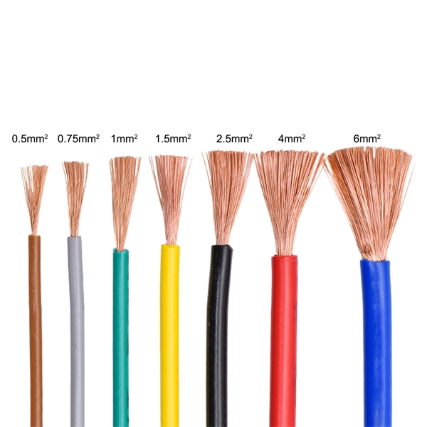
NPO (Near-Packaged Optics) is a transitional technology bridging traditional pluggable modules and CPO. It integrates the optical engine and GPU chip side-by-side on the same high-performance PCB or organic substrate, connected via ultra-short high-speed circuits. Its core concept is to remove digital processing units such as DSPs and CDRs from the module, constructing a purely analog "linear direct-drive" optical link. In the LPO architecture: The transmitter uses a high-linearity driver chip to directly drive the optical modulator, converting the. Near-packaged optics (NPO) helps send data faster. It puts the optical engine close to the switching chip. This makes things work better. NPO lets you upgrade easily. You do not have to redesign your whole system. It lowers energy costs. Among the emerging technologies, LPO (Linear Pluggable Optics), NPO (Near-Packaged Optics), and CPO (Co-Packaged Optics) represent three important stages in the evolution of next-generation data center optical networking. Understanding how these architectures differ is essential for designing. Traditional optical modules typically rely on DSPs (Digital Signal Processors) to handle signal equalization, retiming, and compensation, mitigating attenuation and distortion during transmission. They are not concepts at the same level, but rather.
[PDF]

Cable tray support quantity can be calculated using a simple formula: Support Quantity = Total Length ÷ Support Spacing + 1 20 ÷ 2 + 1 = 11 supports In a typical project, a 20-meter cable tray with 2-meter spacing requires 11 supports. Calculating the cable tray support quantity is a crucial part of electrical installation projects. In complex engineering environments, the. Properly sizing your cable tray is critical for safety and compliance. Our free calculator helps you determine the correct tray size based on NEC and IEC standards. This calculator features an interactive interface with advanced visualizations. Open the full calculator for the best experience. Save your cable tray sizing calculator results as branded PDF. Calculate NEC-compliant wire basket cable tray fill, load capacity, and hardware requirements for professional installations. We independently provide precision steel tools, calculators, and expert resources for steel, metalworking, construction, and industrial projects. IEC 61537 covers cable tray and cable ladder systems for the support and accommodation of cables, while NEC Article 392 governs cable. What is the fill capacity and remaining capacity of my cable tray? Calculate cable tray sizing and fill capacity based on tray dimensions, cable diameter, number of cables, and maximum fill percentage per electrical code. Determine whether cables fit within safe fill limits. Cable tray fill.
[PDF]
If a steel cable tray costs $5 per meter, the cost per foot would be approximately $1. The average cable tray price per meter ranges from $2 to $25, depending on material, type, size, and surface finish. 👉 For bulk orders or project pricing, the cost can be significantly lower. The main cost driver is the material used in manufacturing: 🔹 Galvanized steel is the most common. Although metal pipes (conduit) may appear cheap initially, they tend to be the most costly option when the job is finally complete, since they consume a lot of time to install. Here is how the three main systems compare when looking at the total bill. Why is Conduit So Expensive? Wires go through a. How can we improve? Choose from our selection of ladder cable trays, including cable and hose trays, heavy duty open cable and hose carriers, and more. Same and Next Day Delivery. Aluminum cable ladders are easy to install and cost less than steel cable ladders. Their lightweight construction makes them easy to work with and transport. This is advantageous because it saves on installation costs and time. Cable trays are vital in electrical installations, providing secure pathways for power, communication, and control cables across residential, commercial, and. Cable ladder trays have side rails with rungs to route and support cable. These trays also provide free air flow to prevent overheating, which could damage the cable. They mount overhead or under.
[PDF]

This video shows real on-site footage of electrical installation, demonstrating safe and standardized wiring methods used by professionals. more Learn how to wire a distribution box step by step! This video shows real on-site footage of. Connecting a distribution box involves several steps to ensure proper electrical flow. Follow this guide for a clear and safe connection process: Before starting, always ensure the main power is turned off to avoid electrical shock. Fix the box securely to the wall, ensuring it's at an accessible. An electrical panel box, also known as a breaker box or a distribution board, is a crucial component of any electrical system. It serves as a central hub for distributing electricity throughout a building, ensuring that power is delivered safely and efficiently to all the required locations. In this guide, we'll break down everything you need to know to install a distribution box correctly and confidently. Choose the right box based on environment (indoor/outdoor), load capacity, and durability. Check for proper IP/NEMA ratings and material quality. Whether you're an electrician or a DIY enthusiast, this guide will help you understand the basics of home electrical distribution. Material preparation: Prepare the required circuit breakers, wires, wiring ties and other materials, and ensure that they meet the design drawings and installation requirements. Location determination:.
[PDF]
Click Systems tab Electrical panel Cable Tray. From the Type Selector, select the cable tray type, with or without fittings. On the Options Bar, specify the width, height, offset, or bend radius. more. I am preparing Cable Tray Drawing where i need to provide Cable tray tags on each tray. for that I have Modified default tray Tag family as per my requirement. I use “Comment” Parameter to to tag my cable trays. in my Model there are many Trays and it is very much lengthy and time consuming task. Understand how to model a cable tray using the systems tab in the electrical section for effective coordination, especially in the electrical room. Learn how to set the middle elevation, draw through the room, avoid conflicting elements, and create a detailed and clear visualization of the cable. Sized for the cable fill of the runs it carries. Above lights, below ducts — coordinate with ceiling plenum. Tees, crosses, and reducers handle every direction change. Noble Desktop's Revit MEP Certification Course covers Revit fundamentals — a strong foundation before specializing in mechanical. Join this channel to get access to perks: This lesson walks through how to start a project and properly set up for Electrical Cable Tray design in Revit 2025. It focuses on template selection, component availability, and basic setup steps. Start With the Right Template Opens a new project and.
[PDF]

In this video, we'll show you how to connect an energy meter to a distribution board (DB) safely and efficiently. energy meter connection with distribution box How to Connect an Energy Meter to Your Distribution Box Easily Steps to Properly Connect Your Energy Meter to a Distribution Box. It plays a vital role in ensuring the safe and efficient distribution of electricity throughout the premises. What is the wire from the meter to the breaker box? Also. Always begin with disconnecting the main supply before accessing any enclosure containing distribution components. This prevents arc faults and ensures safety when modifying or inspecting current paths. This “meter to panel” wiring establishes the pathway for all incoming electrical power from the grid to the home. Its primary function is to safely and reliably. Distribution Board aslo know as “Panel Board”, “Switch & Fuse Board” or “Consumer Unit” is a box installed in the building containing on protective devices, such as circuit breaker, fuses, isolator, switches, RCDs and MCBs etc. The electric main supply (230V AC & 120V AC in US) is connected through. Changed Texas's reference diagram for the 3 wire network 120/208 Volt single phase self-contained Revised Figures 13, 14, 14b. Limited the meter location from pad mount transformer for PSO. Removed unistrut being listed as an alternative means for mounting the meter box. APCo and TX do not allow.
[PDF]

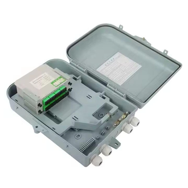
The compact 1 port ftth fiber termination box can hold 2 cores splicing, termination and coil up to 30 meters long for cable management in FTTH network. The 1 port fiber termination box is available for fiber optic cable coiling, it is great to connect optical cable and pigtail and protect fiber splices from damage. It is small, lightweight, and offers the function of fiber splicing, storage, and termination, mainly used in residential buildings. The maximum distance for single mode fiber optic cable can extend up to several hundred kilometers, making it ideal for long distance data transmission. One type of single mode fiber is known as “G. 652,” which is commonly used in telecommunications networks. Here are some general guidelines: 1. The shorter distance accounts for the. A fiber optic distribution box (FDB) is a protective enclosure for managing fiber optic cables. It organizes connections, splices fibers, and distributes signals in networks like FTTH (Fiber-to-the-Home) or FTTB (Fiber-to-the-Building). It acts as a central point for terminating, splicing, and distributing these cables, providing necessary protection and. The Fiber Optic Association, Inc. (FOA) was founded in 1995 to help develop the workforce to build the fiber optic networks to support a rapid expansion in communications and the Internet. The charter of the FOA was to promote professionalism in fiber optics through education, certification, and.
[PDF]

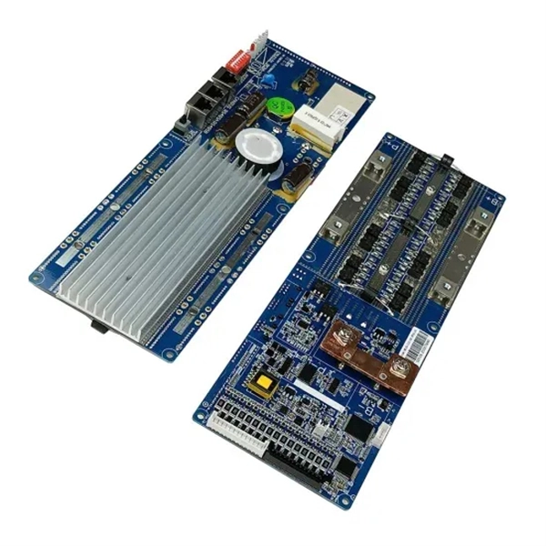
Check the electrical load and ensure that the sensors do not exceed the 10 Amp maximum. Check each wire for damage that may lead to a short. Check the tightness of electrical connections along the power. Issue: Frequent tripping of circuit breakers is one of the most common issues in distribution boards. It can occur due to overloaded circuits, short circuits, or ground faults. Solution: Identify the Cause: Check if the breaker is tripping due to overloading. Internal Inspection Open the distribution box and check for dust and debris accumulation. Inspect circuit breakers for proper operation. Ensure all connections are tight and secure. Each circuit breaker protects a specific circuit in your home, preventing excessive current from damaging wiring and. MDB is panel under power distribution system which consists of a fuse, circuit breakers and ground leakage protection units. Where electrical energy is taken from a transformer or an upstream panel to distribute electrical power to numerous individual circuits or consumer points. Various types of panels exist in every electrical.
[PDF]

In the 2020 NEC ®, no more than 18 inches of cable length is allowed between the cable entry to the box and the closest cable support (see image). Below is a preview of the NEC®. ORG for the complete code section. The previous code language could technically allow an unlimited length of coiled up NM cable inside the wall as long as it was secured within 12 inches of the box. This code is based upon the type of box, wires, wire sizes, wire clamps and conduit fittings. Adjustments are made for the ground wire as you will see in the. Calculate and select the right number and spacing of cables for junction boxes using NEC guidelines to ensure safe, code-compliant electrical installations. This step keeps your project safe and. According to the National Electrical Code (NEC), the conductor must be long enough to extend outside the box's opening. This length allows enough room to connect, splice, or terminate wires without strain or damage. If wires are too short, they may fail inspection or create hazards during. The length of wire left inside an electrical box is a matter of strict compliance, safety, and functionality. Having the correct amount of slack ensures that future maintenance, repairs, or device replacements can be performed without difficulty. Proper electrical box fill calculations are critical for code compliance and safety in both residential and commercial installations.
[PDF]

Non-polarizing beamsplitters are specified by their splitting ratio, i. the ratio of P-polarized light to. A beam splitter or beamsplitter is an optical device that splits a beam of light into a transmitted and a reflected beam. It is a crucial part of many optical experimental and measurement systems, such as interferometers, also finding widespread application in fibre optic telecommunications. a laser beam) into two (or sometimes more) beams, which may or may not have the same optical power (radiant flux). Different types of beam splitters exist, as described in the. The collimated incident laser beam passes through the beam splitter, and the output beam is emitted at a specific separation angle on the output beam array. The following figure is an introduction to the basic settings of a beam splitter. Circular beamsplitters, plate beamsplitters and cube beamsplitters can be purchased for polarizing or non polarizing beamsplitting. Beamsplitters are optical components used to split incident light at a designated ratio into two separate beams.
[PDF]
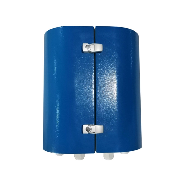
A step-by-step guide to the proper installation of a dry type transformer, covering location, mounting, connections, and safety checks. Ensure a safe and reliable setup. In this guide, we will walk you through the process of connecting a dry type transformer, ensuring you understand the wiring and installation steps involved. Before diving into the connection process, it's essential to have a basic understanding of dry type transformers. These transformers work by. Proper installation is absolutely critical to the safe and reliable operation of a dry type transformer. While the work must be performed by a qualified electrician, understanding the key steps is beneficial for project managers and facility owners. An incorrect installation can lead to equipment. See how CHBEB engineers install high-conductivity copper busbars with precision. Each connection is securely fastened, ensuring minimal resistance and maximum efficiency ⚡. The input and output three-phase power lines should be connected to phase A, phase B, and phase C respectively according to the color of the bus bar of the transformer terminal block, yellow, green, and red. In this article, we'll walk through the step-by-step.
[PDF]
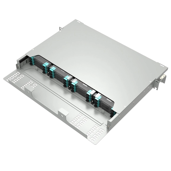
Remove the module from the receiver frame. Use the Allen wrench to remove the module cap screws located at the top, middle and bottom of the module (Figure B). For 37 and 16/16 position use a Phillips screw driver to remove the (2) 2-56 screws. Terminating fiber optic cables essentially means putting connectors on fiber optic cable so that you can connect the cable to various devices or network components. Think of it as the equivalent of connecting the dots in a complex puzzle; without proper termination, the whole system can break down. How to remove/disconnect fibre cable from Telus modem? Pull the green thing from the metal thing If you pull it out make sure to put the fiber connection in a plastic bag or blow it with air before plugging it back in, Fiber laser modules and a single spec of dust/lint/crumb can affect your speeds. Terminating fiber optic cable is a crucial step in the installation process, as it ensures a reliable and efficient connection. The contact can only be installed from one side. Ensure that the contact is squared up with the corresponding module location. Once in place, pull the wire. The transceivers for the router are hot-removable and hot-insertable field-replaceable units (FRUs). After you remove a transceiver or when you change the media-type configuration, wait for 6. IN THIS VIDEO I WILL SHOW YOU How to Disconnect Optical Fiber Cables from the Connector #DISCONNECTOPTICALFIBER.
[PDF]
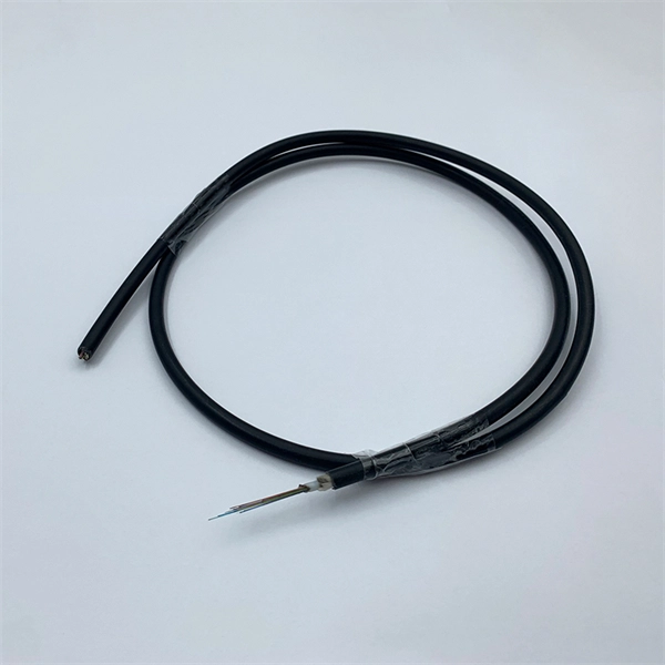
A 12-core ADSS cable for short spans (≤100 meters) might cost around $0. 35 per meter, using a standard double PE jacket and basic aramid strength members. Discover the latest ADSS fiber optic cable prices for various spans and core counts. Get competitive quotes, understand cost factors, and choose the best solution for your aerial fiber project. As global demand for faster and more reliable broadband expands, ADSS (All-Dielectric Self-Supporting). ADSS 24-wire anti-rodent type fiber optic cable, this design combines enhanced optical reliability with the highest degree of rodent resistance available in an all-dielectric cable. ADSS FRP Defender-Anti Rodent also can be used as an all-dielectric direct buried cable solution. Our team is. Fiber Optic Cable 258 Original Std ADSS Flex-Span ADSS New Std ADSS Applications • Electric utility transmission lines – Typically framed under conductors • EHV environments – Tracking-resistant options available Features • Up to 432 fibers in cable – Gel-Free Buffer Tube options available – up to.
[PDF]
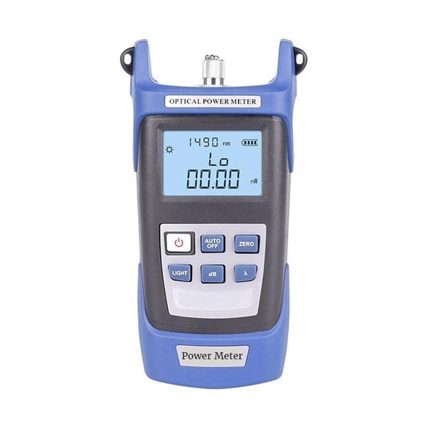
A 150 m launch/tail cord will work for fiber links of 2 km or less, typically found in enterprise networks. This document provides instructions for the fiber cable technician to properly perform fiber cable preparations, rout-ings, splicing, terminations and connections within a Charles Industries' Fiber Distribution Point (CFDP2) EL24 Pedlock pedestal with a 10” dome. This model, shown in Figure 1. A: The fiber type of launch and tail cords must match the fiber type used in the fiber link under test. Q: How long should a launch or tail cord (launch or receive cable) be? The particular model OTDR you are using. Pigtails are available in various fiber types, such as single-mode or multi-mode, and connector types, including SC, LC, ST, or FC. These components are often left dangling, unused, or improperly labeled, and can be found coiled inside fiber distribution panels. The most efficient way to terminate a fiber run is by using a pigtail.
[PDF]