
Optical Modules are hot swappable, and you do not need to power off the device when replacing Optical Modules. Optical Modules are electrostatic-sensitive components. In most enterprise networking environments, the ability to replace hardware without shutting down equipment is essential for maintaining uptime. Do not insert an optical module reversely. Gently pull the module latch or release ring, depending on the module design. Remove the module in a straight motion – do not twist or pull at an angle. Reapply the. Before you begin removing a transceiver from the router, ensure that you have taken the necessary precautions for safe handling of lasers (see Laser and LED Safety Guidelines and Warnings). Ensure that you have the following parts and tools available: The transceivers for the router are. An optical module implements optical-electrical conversion, enabling optical transmission between a DRH and other devices. Disconnecting the optical fibers interrupts the transmission of CPRI signals.
[PDF]
This article compares typical cost ranges across speeds and transceiver types, explains why prices vary, and gives practical guidance for choosing the right optics for a given budget and performance requirement. This article helps network architects and procurement teams run a practical cost analysis for implementing Open RAN using pluggable optical modules across fronthaul and midhaul. All price bands below are market-observed ranges (OEM-branded vs. As per our latest research, the 25G Fronthaul Optical Module market size reached USD 1. 42 billion globally in 2024, demonstrating robust growth driven by the accelerating deployment of 5G wireless networks and expanding data center infrastructure. The market is projected to grow at a CAGR of 18. 7% from 2025 to 2033, reaching a forecasted value of USD 4. 47. The 5G fronthaul optical transceiver modules market is experiencing rapid evolution driven by the global rollout of 5G networks. These modules form the backbone of high-capacity, low-latency communication infrastructure essential for 5G deployment.
[PDF]

It involves encapsulating the optical chip in a metal box filled with inert gas (usually helium) to protect the optical elements from external environmental influences and enhance heat dissipation. COB, BOX, and TO-CAN packaging each offer unique advantages tailored to specific applications. COB packaging integrates components directly onto a PCB, enabling miniaturization and cost efficiency. BOX packaging seals optical chips in a metal enclosure with inert gas, ensuring long-term stability. The COB process refers to a technology that directly mounts bare chips onto a printed circuit board (PCB), connects them via gold wire bonding, and then encapsulates and protects the chips and wires using organic adhesive. Compared with conventional processes, the COB process offers high packaging. Box, COB, and TO can are currently the most prevalent packaging forms for optical components. Box packaging, also known as hermetic sealing, has a long history. Common optical device packaging methods include COB (chip-on-board packaging), BOX and coaxial packaging. What is COB technology? COB (Chip on board) is a form of packaging that directly bonds the. The invention provides an SFP28 SR optical module structure of a COB process, and belongs to the field of optical module structures. The micro-optical module comprises a shell, an unlocking mechanism, an EMI shielding structure, a circuit board, a micro-optical module arranged at one end of the.
[PDF]

In the photopic region, luminous efficacy peaks at 683 lumens per watt at 555 nm. In fact, the lumen is defined in terms of the power at 555 nm (frequency of 540 × 1012 Hz). Luminous efficacy is defined as the luminous flux produced per unit of power, usually electrical power, measured in lumen per watt (lm/W). It is explained how the overall efficacy of a lighting installation is often lower than that of the light source itself due to factors like light absorption in. Luminous efficacy is a measure of how efficiently a light source produces visible light. Depending on context, the power can be either the radiant flux of the source's output, or it can. The relative spectral responsivity of the human visual system was first defined by the Commission Internationale de l'Éclairage (CIE, the International Commission on Illumination) in 1924. The response of the eye as a function of frequency is called the luminous efficacy of the eye. It has been tabulated for both the light-adapted (photopic) case and the dark-adapted (scotopic) case. Source: Table 6-1 of.
[PDF]
This manual describes Inspect, a command-line tool for debugging TNS C/C++, COBOL, FORTRAN, Pascal, Screen COBOL, and TAL programs and snapshots on HP NonStopTM TNS/R and TNS/E systems. MFT (Mellanox/NVIDIA Firmware Tools) is a set of firmware management utilities for querying firmware details, performing firmware upgrades, and other configuration tasks. It includes four main components: mst, mlxburn, flint, and Debug Utilities. For full specifications, refer to the official. All commands were tested on HP/Aruba 5400 switches (specifically 5406Rzl2), but will work on any model with recent firmware versions (16. x or newer), except for the hardware features unavailable on smaller models, like VSF. This publication supports J06. 03 and all subsequent J-series RVUs, H06. Show general info: current CPU load, uptime, memory used/free, software. The HP 1-Port 1GbE Flex IO NIC is designed to work in the Flex IO port of select HP systems. Refer to platform specifications for compatibility. It utilizes a Realtek RTL8153 10/100/1000 Ethernet controller to provide an additional 1GbE LAN Port. 3az-2010, also known as Energy. HPE Insight Diagnostics is a hardware diagnostic tool. To start iLO with keyboard and monitor connected to the box - press F8 while booting Invoke virtual serial port. Starting text console. Press 'ESC (' to return to the CLI Session.
[PDF]

These general purpose fiber clamps provide easy means for incorporating glass or plastic optical fibers into optomechanical post assemblies or SM1-threaded components. The precision V-groove and rubber pad are designed to clamp onto the buffer of single mode or multimode fibers without damaging. Harwin supplies a range of surface-mount shield can clips to provide a straight-forward, easy-to-use board-level shielding solution. The combination of SMT clips with a shield can provides a simple and cost-effective method of shielding vulnerable or EMI-radiating board components. Harwin's shield. Check each product page for other buying options. 2-piece kit Fiber optical thermal stripper M8 & fiber optical cleaning clip compatible with bare fiber/bundle and ribbon fiber for 1-48 core dual heating mode and 8-level temperature regulation. Need help?. FPH Fiber Chucks and Holders are designed to terminate bare optical fibers and provide precise coupling and mounting within optical systems. Compatible strain relief boots and fiber clamps are also available. Clamps are larger than clips and designed to hold multiple cables and wires together. Blind plugs are used to close. 1-800-363-1992 Have any questions? Talk with us directly using LiveChat.
[PDF]
The SFP-10G-ER transceiver module is the proven, standards-based workhorse for extending 10 Gigabit Ethernet up to 40km over cost-effective single-mode fiber. This hot-pluggable SFP+ transceiver is engineered to transmit 10Gbps data streams over single-mode fiber (SMF) for link lengths up to 40 kilometers, making it indispensable for metro Ethernet, campus backbone networks, enterprise data center interconnects (DCIs), and telecom access networks. 10GBASE-LR SFP+ Module: 10Gb/s data rate, Single-Mode, duplex LC connector, 1310nm wavelength, the transmission distance up to 10km, working temperature: 0℃ ~ 70℃, Tx Power (dBm): -6. Equipped with an LC connector. Experience reliable high-speed networking with the VIVOTEK SFP-2000-SM13-10, a 10 Gigabit Mini GBIC designed for enhanced performance. Utilizing 10GBase-X technology, it delivers data transfer speeds up to 10 Gbps over compatible cables, ensuring efficient and scalable connectivity. This module. The 10 Gigabit Singlemode SFP+ Transceivers provide high-performance, reliable connectivity for modern 10 Gigabit Ethernet (10GbE) networks. These transceivers are designed for singlemode fiber, offering superior performance over long distances. Whether you're working on data centers, campus. These SFP transceiver modules come in a metal housing that reduces electromagnetic interference and increases their durability.
[PDF]

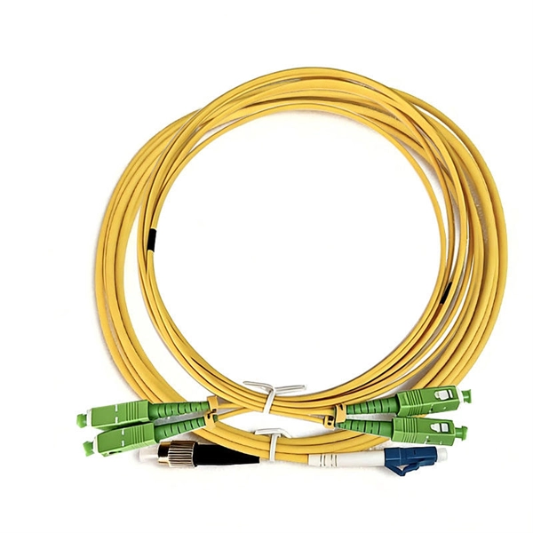
Usually, the 10G/25G grey light optical modules with a short transmission distance are applied for connecting AAU/DU with WDM/OTN/SPN. The connections between WDM/OTN/SPN network devices can be achieved by 10G/25G/50G/100G dual-fiber or single-fiber bidirectional. Compared with Draft A (2013-07-30), this issue includes the following new topic: 2. This section describes engineering specifications of an AAU, including input power and equipment specifications. 7. In 2/3/4G networks, 10Gbps optical modules are generally enough for CPRI interfaces. In 5G networks, CPRI is also upgraded to eCPRI. Currently, 5G of the bearer network mainly uses 25Gbps optical modules. Next, ETU-LINK will introduce the types of optical modules used by 10G SFP+ and 25G SFP28. What is the difference between the 5G bearer network and the traditional optical transmission network? The main difference is that 5G fronthaul needs to support CPRI/eCPRI protocol. Most of the AAU of 5G base stations are deployed outdoors. In order to resist harsh environments such as high. The optical modules used to connect BBU and RRU devices are optical modules and optical fibers. Product Versions The following table lists the product versions related to this document. 25G SFP optical module adopts the wavelength of 850nm, with an operating.
[PDF]

Run the following command to view detailed optical module information on the device interface: display transceiver interface <interface-type> <interface-number> verbose The command output is divided into two parts:. Run the following command to view detailed optical module information on the device interface: display transceiver interface <interface-type> <interface-number> verbose The command output is divided into two parts:. When the optical module on an interface is faulty, you can run the display commands to view information about the optical module. Related Information Video Identify a Huawei-Certified Optical Module Run the display transceiver [ interface interface-type interface-number | slot slot-id ] [ verbose ]. During use, reading optical module information helps understand its real-time operating status, enabling faster troubleshooting of link abnormalities. The following uses the Moduletek SFP-10G-LR module connected to a Huawei S6700 switch as an example to introduce how to read information of the. See the interface module via the optical display command information, including general information of the optical module, manufacturing information, and alarm information. If it is not a Huawei-certified optical module, replace it with a Huawei-certified optical module. If the optical module is installed on a GE port, run the display interfaceGigabitEthernet x/x/x command to view port information when the optical module.
[PDF]

In simple terms, Receiver Sensitivity is the minimum received optical power required at the input of a receiver for the system to achieve a specified performance level, typically defined by a maximum Bit Error Rate (BER). Think of it like listening to a distant radio station. The standards body governing the application sets this specified BER. For example, SONET specifies that the BER must be 10 -10 or better. Optical modules form the backbone of modern data center networks, enabling ultra-high-speed data transmission between servers, switches, and storage devices. In optical link design, the receiver performance parameters are like vital signs of the link, directly determining the reliability and. Receiver sensitivity shows the weakest signal your device can find. Good sensitivity gives stronger connections, even with weak signals. Always look at the dBm value in product details. A lower dBm means better receiver sensitivity. This helps you pick the best device. It denotes a module's capability to function in challenging environments and aids network operators in determining the system's maximum reach or link margin.
[PDF]
Run the display device esn command to view the chassis serial number. The command format may vary depending on the. This document describes how to obtain the serial numbers of S series switches running V600. The serial numbers of devices are necessary for network construction and device maintenance. GigabitEthernet1/0/2 FINISAR CORP. FTLF1619P1BCxxxx PR7xxxx 2014-02-21 NO GigabitEthernet1/0/10. This topic describes the encapsulation types of optical modules on WDM products Small form-factor pluggable (SFP) optical modules are compact, hot-swappable, low-speed optical modules. They comply with the specifications defined in the multi-source agreement (MSA) and support synchronous optical. Here are the common commands to use to display hardware-related information on Huawei Routers. The inventory information such as serial number, product code,optical module,device, power,voltage,temperature,fan, CPU and memory are very important on operation and troubleshooting purposes. Your email. ALL DIMMING BALLASTS TO BE LUTRON ECOSYSTEM, ECOSYSTEM H-SERIES, OR HI-LUME 3D TYPE. TO CONFIRM ALL CIRCUITING REQUIREMENTS. ARCHITECT TO VERIFY QUANTITY, LOCATION & FINISH OF ALL CONTROLS. This paper presents an Echo State Network (ESN)-Driven joint decision strategy for a configurable security Non-Orthogonal Multiple Access (NOMA) optical communication system. To address security vulnerabilities, a configurable key iteration scheme is introduced, achieving temporal interleaving of.
[PDF]

These installation instructions provide overview and specification information for small form-factor pluggable (SFP/ SFP+/SFP28) modules, as well as instructions for installing and removing the modules. Small form factor transceiver modules (including SFP, SFP+, and SFP28 modules) plug into the SFP. Some Extreme Networks switches support the use of 25 Gb SFP28 pluggable optical modules. Each module provides one 25-gigabit transmit and receive channel. Use of 25Gb SFP28 modules in QSFP28 ports requires the use of the QSFP28 to SFP28 adapter (part no. Use only Extreme Networks-certified. The ESR SFP28 module provides a 25 Gb optical connection using an LC duplex optical connector over one pair of OM3 or OM4 multimode fibers. One data lane operates in each direction, at 25 Gbps up to 200 meters using OM3 fiber or up to 300 meters using OM4 fiber. The fiber-optic SFP modules contain a laser that is classified as a “Class 1 Laser Product” in accordance. LINK-PP offers a full range of optical transceivers and SFP module for modern data centers, telecom networks, and enterprise infrastructures. Our portfolio spans data rates from 1G to 400G, including SFP, SFP+, SFP28, QSFP+, QSFP28, QSFP-DD, and OSFP modules, designed for both single-mode and.
[PDF]

One of the core advantages of MPO patch cords is their high-density integration. Traditional patch cords have only 1-2 cores per cord, while MPO patch cords can integrate 12-48 cores, enabling multi-port connections with a single cord. Fiber cores are the heart of fiber optic cables, transmitting light signals that carry data. Made from either high-quality glass or plastic, the core plays a critical role in determining the cable's performance. The total number of cores for a 1pc fiber patch cable is calculated as the number of. Multi-core patch cords are fiber assemblies containing multiple fibers within a single cable jacket, typically available in 4, 6, 12, and 24-fiber configurations. The outer sheath is clearly marked with core count indicators. MTP/MPO cables are a class of high-density multi-core fiber optic connectivity solutions widely used in data centers and telecom networks, which are designed to achieve fast connection of multi-core fiber optics through a single interface. In the context of accelerating digitalization, the rational. The 16-core MPO patch cord, a high-density optical fiber connector, has become an ideal choice for 400G networks and beyond due to its superior optical performance, flexible compatibility, and efficient cabling capabilities. This report analyzes the key technical parameters, primary application.
[PDF]

Its typical transmission distance is 20km or 40km. For instance, some ethernet switch manufacturers refer to the 1000BASE-LH SFP as the 1G 1310nm 40km SFP transceiver, which indicates the module's transmission distance and wavelength. The 10G SFP+ dual-fiber optical module is a small pluggable optical transceiver that adopts a dual-fiber bidirectional design. It completes signal transmission (Tx) and reception (Rx) through two independent optical fibers, ensuring the stability and reliability of signal transmission. An SFP (Small Form-factor Pluggable) module transmits data over fiber using specific wavelengths and power levels, which directly influence how far the signal can travel before degradation occurs. This is why two. If the optical module works at a wavelength near 850nm (880nm) or 910nm (940nm), then the module is a multi-mode fiber (MMF) optical transceiver, and if the working wavelength is 1310nm or 1550nm, it is a single-mode fiber (SMF)optical module. Generally, the maximum transmission distance(generally. The transmission distance of optical transceiver modules is divided into short distance, medium distance, and long distance. A 1-core module uses a single fiber core for data transmission, while a 2-core module uses two cores. o Think of a highway. Chromatic dispersion This is a key factor affecting single mode fiber distance.
[PDF]

This guide provides a clear, step-by-step explanation of how to install an SFP module correctly, based on real-world deployment practices. The fastest way to do so is by unplugging the power plug from the power outlet. This is a Class A product. In a domestic environment, this product might cause radio interference in which case the user might be required to take adequate measures Electric shock hazard. This equipment is to be. This Quick Guide covers the model: CCR2004-16G-2S+PC. You can find the product model name on the case label (ID). Or scan the QR code with your mobile phone. lv/um The most important. The Installation of the equipment must comply with local and national electrical codes. Please read the mounting instructions carefully before beginning installation. Failure to use the correct hardware or to follow the correct procedures. The CCR2004 is a high-performance multicore router with twelve 10G SFP+ ports and two 25G SFP28 ports. Before you work on any equipment, be aware of the hazards involved with electrical circuitry, and be familiar with standard practices for preventing accidents. It covers critical preparation checks, proper insertion techniques, hot-swap and safety considerations, common installation mistakes, and practical. The Cisco 8000 series routers support both ZR and ZR+ modules. The Cisco 8200 Series uses a single Cisco Silicon One ASIC to deliver full routing functionality. These fixed port, high-density routers provide 10.
[PDF]