
This comprehensive guide breaks down the internal structure, core components (TOSA, ROSA, lasers), and operational mechanisms of SFP optical modules, enriched with technical insights and real-world applications. SFP (Small Form-factor Pluggable) optical modules are compact, hot-pluggable transceivers that enable network equipment to connect seamlessly to fiber and copper links. As a leading provider of optical communication solutions, Weunion integrates these. One vital element in the data communication sector is the Small Form-factor Pluggable (SFP) module. In this blog, we will explore the inner workings of these modules, with a particular focus on three essential optical components: TOSA, ROSA, and BOSA. SFP modules are small, hot-swappable devices. Optical modules are devices used to connect network devices, transmit and receive data between network devices, and can be used to convert optical and electrical signals. The optical module is a very important component in an optical communication system. Think of it as the “translator” for your network equipment, converting electrical signals into optical signals. available with a variety of types of copper SFP and fiber SFPs, SFP+. This transceiver module is compliant wi h the small form-factor pluggable (SFP) multi-source agreement (MSA). They industrial performance with an extended operating temperature range. Through real-time monitoring, the DDM.
[PDF]

When you connect two 1000BASE-T switches with SFP ports to achieve Gigabit Ethernet, there are two methods: through standard Ethernet cable plugged into the built-in Ethernet ports of each switch, or use the SFP ports with a copper SFP module. 🎥 In this video, I show you how to connect two different branded switches using SFP modules and fiber optic cables. Whether you're using Cisco, Planet, TP-Link, D-Link, Ubiquiti, or any other brand — the key is understanding SFP compatibility. Before moving ahead, let us discuss some basics about standard Ethernet cables and 1000BASE-T (IEEE 802. Network topology refers to the way in which the links and nodes of a network are arranged in relation to each other. What Is a 10Gb SFP Module? A 10Gb SFP (Small Form-factor Pluggable) module is a compact, hot-swappable transceiver used to establish high-speed fiber. Did you swap one of the fiber connectors at one of the endpoints? Meaning, take off the housing of the fiber connector, and swap a and b. You'll find SFP / SFP+ specs on the datasheets for the switches. They're free to view and download from Cisco. Cisco also publish a GBIC /. Most modern fiber-enabled network switches require an SFP transceiver module featuring a duplex (two strand) multimode OM3 or duplex single mode OS2 connection with LC connectors. Direct attach cables with pre-terminated SFP connections may also be used. Download the Application PDF SFP transceiver.
[PDF]

Learn how to monitor SFP optical power on Cisco switches, interpret Tx/Rx levels, and troubleshoot fiber link issues. Step-by-step CLI commands, model-specific guidance, and best practices included. In this article, we will break down the key factors influencing TX/RX power, explain how to calculate the optical power budget, and provide actionable insights for optimizing your network's performance using SFP modules. SFP (Small Form-Factor Pluggable) modules are compact transceivers that allow. SFP (Small Form-factor Pluggable) optical modules are compact, hot-pluggable transceivers that enable network equipment to connect seamlessly to fiber and copper links. Even if an interface appears up, degraded Tx/Rx levels can cause intermittent flapping, packet loss, or err-disabled states. Think of it as the “translator” for your network equipment, converting electrical signals into optical signals. The most two important factors of the SFP transceiver: Output power (TX power) and receiver sensitivity (RX sensitivity). The optical TX power is the signal level leaving from that device, which should be within the transmitter power range. The RX sensitivity is the incoming signal level being. In current network communication, SFP optical modules are an indispensable physical foundation for building network channels. They form high-speed channels for optical signal transmission. Therefore, to ensure their.
[PDF]

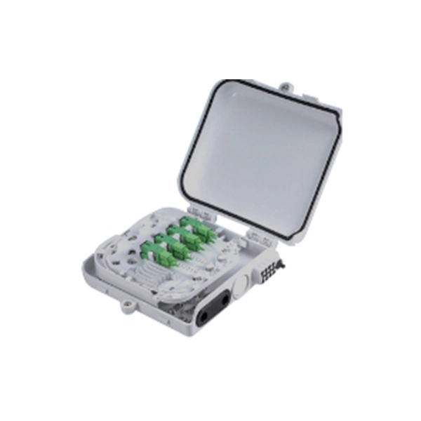
Unlike traditional point-to-point fiber connections, PON systems distribute optical signals from an optical line terminal (OLT) to many optical network units (ONUs) or optical network terminals (ONTs) without requiring active electronic equipment in the distribution network.StatusIn forceYear started2003Latest version(07/10) · July 2010OrganizationOverview G.984 is the series of standards that define the architecture and operation of -per-second–capable (GPON). It is commonly used to implement the link to the customer (the. GPON uses passive optical network (PON) is a access in which a single optical fiber from a central location is shared by multiple end users through one or more in series (cascaded). The standard specifies transmission convergence layer, physical layer requirements, management protocols, and service encapsulation for high-speed fiber access networks. GPON put. In contrast to technology, which deteriorates as the distance between the central office and the household rises, with severe signal loss beyond 3km, all customers may enjoy high-speed network access with.
[PDF]

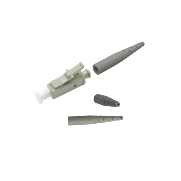
This guide provides a fully updated and industry-ready overview of LC fiber optics, explaining the origin and design of LC connectors, their key features, and the complete ecosystem of LC-based products used in modern networking. It covers LC connectors, LC patch cables, uniboot designs, armored. LC stands for Lucent Connector (also colloquially “Little Connector”). It was introduced by Lucent Technologies to deliver small form factor (SFF) optical connections that match the density of RJ-45 copper ports. 25 mm ferrule (half the size of SC's 2. 5 mm) enables twice the port. Fiber optic connectors are used to the mechanical and optical means for cross connecting fibers. Fiber optic connectors can also be used to join fiber cables to transmitters or receivers. As a small-form-factor (SFF) interface, LC has become the default duplex connector in enterprise LANs, telco closets, and data-center topologies because it balances density, repeatability, and cost. SC connectors were originally designed for FTTH, but they were gradually popularized and used on a large scale due to their small size and convenience. You may find LC connector has a strong family which includes but not limited to LC optical fiber connectors, LC fiber patch cables, LC fiber.
[PDF]

In the photopic region, luminous efficacy peaks at 683 lumens per watt at 555 nm. In fact, the lumen is defined in terms of the power at 555 nm (frequency of 540 × 1012 Hz). Luminous efficacy is defined as the luminous flux produced per unit of power, usually electrical power, measured in lumen per watt (lm/W). It is explained how the overall efficacy of a lighting installation is often lower than that of the light source itself due to factors like light absorption in. Luminous efficacy is a measure of how efficiently a light source produces visible light. Depending on context, the power can be either the radiant flux of the source's output, or it can. The relative spectral responsivity of the human visual system was first defined by the Commission Internationale de l'Éclairage (CIE, the International Commission on Illumination) in 1924. The response of the eye as a function of frequency is called the luminous efficacy of the eye. It has been tabulated for both the light-adapted (photopic) case and the dark-adapted (scotopic) case. Source: Table 6-1 of.
[PDF]

Optical Modules are hot swappable, and you do not need to power off the device when replacing Optical Modules. Optical Modules are electrostatic-sensitive components. In most enterprise networking environments, the ability to replace hardware without shutting down equipment is essential for maintaining uptime. Do not insert an optical module reversely. Gently pull the module latch or release ring, depending on the module design. Remove the module in a straight motion – do not twist or pull at an angle. Reapply the. Before you begin removing a transceiver from the router, ensure that you have taken the necessary precautions for safe handling of lasers (see Laser and LED Safety Guidelines and Warnings). Ensure that you have the following parts and tools available: The transceivers for the router are. An optical module implements optical-electrical conversion, enabling optical transmission between a DRH and other devices. Disconnecting the optical fibers interrupts the transmission of CPRI signals.
[PDF]

In simple terms, Receiver Sensitivity is the minimum received optical power required at the input of a receiver for the system to achieve a specified performance level, typically defined by a maximum Bit Error Rate (BER). Think of it like listening to a distant radio station. The standards body governing the application sets this specified BER. For example, SONET specifies that the BER must be 10 -10 or better. Optical modules form the backbone of modern data center networks, enabling ultra-high-speed data transmission between servers, switches, and storage devices. In optical link design, the receiver performance parameters are like vital signs of the link, directly determining the reliability and. Receiver sensitivity shows the weakest signal your device can find. Good sensitivity gives stronger connections, even with weak signals. Always look at the dBm value in product details. A lower dBm means better receiver sensitivity. This helps you pick the best device. It denotes a module's capability to function in challenging environments and aids network operators in determining the system's maximum reach or link margin.
[PDF]
If your high beams are not working, the most likely cause is a blown fuse or a burned-out bulb — both of which you can check yourself in under 15 minutes. That said, there are seven possible culprits, ranging from simple fixes you can handle at home to electrical faults that need a mechanic's. To be clear, I am not saying the highbeams are turning on and off, I mean the actual intellibeam system as indicated by the headlight symbol with the "A" in it on the DIC. When the system is on, the highbeams most of the time will work 100% as expected activating and deactivating when appropriate. Automatic high beam (AHB) systems, sometimes marketed under proprietary names like IntelliBeam or SmartBeam, are designed to enhance nighttime visibility by automatically switching between high and low beams. These systems use forward-facing cameras or sensors to detect light sources from oncoming. Affiliate programs and affiliations include, but are not limited to, the eBay Partner Network. 2021+ Ford F150 Discussion of the 14th generation F150. LED headlight High Beam Failure noticed that high beam on the drivers side LED headlight stopped working. Hooked up the reader and found fault code. Auto High Beam is a safety feature that controls the headlight operation and lights up the road in front using low and high beams. There is too much lag time for enabling the high beams. I just use the old skool manual headlights mode and switch my high beams as.
[PDF]

Run the following command to view detailed optical module information on the device interface: display transceiver interface <interface-type> <interface-number> verbose The command output is divided into two parts:. Run the following command to view detailed optical module information on the device interface: display transceiver interface <interface-type> <interface-number> verbose The command output is divided into two parts:. When the optical module on an interface is faulty, you can run the display commands to view information about the optical module. Related Information Video Identify a Huawei-Certified Optical Module Run the display transceiver [ interface interface-type interface-number | slot slot-id ] [ verbose ]. During use, reading optical module information helps understand its real-time operating status, enabling faster troubleshooting of link abnormalities. The following uses the Moduletek SFP-10G-LR module connected to a Huawei S6700 switch as an example to introduce how to read information of the. See the interface module via the optical display command information, including general information of the optical module, manufacturing information, and alarm information. If it is not a Huawei-certified optical module, replace it with a Huawei-certified optical module. If the optical module is installed on a GE port, run the display interfaceGigabitEthernet x/x/x command to view port information when the optical module.
[PDF]

Usually, the 10G/25G grey light optical modules with a short transmission distance are applied for connecting AAU/DU with WDM/OTN/SPN. The connections between WDM/OTN/SPN network devices can be achieved by 10G/25G/50G/100G dual-fiber or single-fiber bidirectional. Compared with Draft A (2013-07-30), this issue includes the following new topic: 2. This section describes engineering specifications of an AAU, including input power and equipment specifications. 7. In 2/3/4G networks, 10Gbps optical modules are generally enough for CPRI interfaces. In 5G networks, CPRI is also upgraded to eCPRI. Currently, 5G of the bearer network mainly uses 25Gbps optical modules. Next, ETU-LINK will introduce the types of optical modules used by 10G SFP+ and 25G SFP28. What is the difference between the 5G bearer network and the traditional optical transmission network? The main difference is that 5G fronthaul needs to support CPRI/eCPRI protocol. Most of the AAU of 5G base stations are deployed outdoors. In order to resist harsh environments such as high. The optical modules used to connect BBU and RRU devices are optical modules and optical fibers. Product Versions The following table lists the product versions related to this document. 25G SFP optical module adopts the wavelength of 850nm, with an operating.
[PDF]
This manual describes Inspect, a command-line tool for debugging TNS C/C++, COBOL, FORTRAN, Pascal, Screen COBOL, and TAL programs and snapshots on HP NonStopTM TNS/R and TNS/E systems. MFT (Mellanox/NVIDIA Firmware Tools) is a set of firmware management utilities for querying firmware details, performing firmware upgrades, and other configuration tasks. It includes four main components: mst, mlxburn, flint, and Debug Utilities. For full specifications, refer to the official. All commands were tested on HP/Aruba 5400 switches (specifically 5406Rzl2), but will work on any model with recent firmware versions (16. x or newer), except for the hardware features unavailable on smaller models, like VSF. This publication supports J06. 03 and all subsequent J-series RVUs, H06. Show general info: current CPU load, uptime, memory used/free, software. The HP 1-Port 1GbE Flex IO NIC is designed to work in the Flex IO port of select HP systems. Refer to platform specifications for compatibility. It utilizes a Realtek RTL8153 10/100/1000 Ethernet controller to provide an additional 1GbE LAN Port. 3az-2010, also known as Energy. HPE Insight Diagnostics is a hardware diagnostic tool. To start iLO with keyboard and monitor connected to the box - press F8 while booting Invoke virtual serial port. Starting text console. Press 'ESC (' to return to the CLI Session.
[PDF]

In this tutorial, I will show you how you can connect the Optocoupler to Arduino, read the data as Analog or Digital, and if necessary convert the analog values to digital, and how to reduce noise from the sensor. The Infrared Slotted Optical Optocoupler Module is a device that uses infrared light to transmit signals between two electrically isolated circuits. It consists of an infrared emitter (LED) and a photodetector (phototransistor) housed in a slotted enclosure. When an object passes through the slot. Slotted Optocouplers (Photo Interrupters) are very useful sensors, often included in Arduino projects to detect position of moving objects, measure speed of rotation, or linear motion, frequency of events, and many others. They are easy to use, but it is important to understand how they work, so. This tutorial is a comprehensive, practical guide to the Speed Sensor / Tacho Sensor (Slot-Type Optocoupler) (Leobot Product #245). Moreover, a simple application is programmed that shows how to wire and how to program an Arduino when working with the module. In this tutorial, the module is used as an “digital input board”. If you want to use the. In this project, I will talk about Phototransistor Optical Interrupter Switches (Opto Coupler) Module, how this module works and helps in determining the speed of a rotating object and finally I will show you how to Interface Optical Interrupter Switch Sensor with Arduino and measure the speed of a.
[PDF]

This video shows real on-site footage of electrical installation, demonstrating safe and standardized wiring methods used by professionals. Whether you are setting up a new telephone line or troubleshooting an existing one, understanding the basics of wiring is essential. In this article, we will explore the key components of a telephone line box and the. In this video, we'll walk you through the process of wiring a home distribution box with a detailed connection diagram. What is Distribution Board? Distribution board. mounted in OnQ Service Center Enclosures and come in several different telecom/video combinations; an example (6+8) is shown yle fittings for connecting incoming and outgoing cables. ve an 8 position 110 punch-down connector for incoming 4 ine service and 110 (8) position punch-down connectors. With the right wiring diagram, you can easily complete the job and get your outside phone box up and running in no time. If you're looking for a wiring diagram to help you install an outside phone box, then you've come to the right place. From there, the wiring is divided into separate lines for different areas of the house, such as bedrooms, living rooms, and kitchens. Each line is then connected to a.
[PDF]
The CFP, short for C form-factor pluggable, is a multi-source agreement to define the form-factor of the optical transceiver for high-speed digital signal transmission. CFP transceivers are defined by CFP MSA to enable 40 Gb/s, 100 Gb/s and 400 Gb/s applications. The c stands for the Latin letter C used to express the number 100 (centum), since. What is a CFP optical module? Is it still relevant in 2026? And when should you choose it over newer alternatives? This guide is designed to answer those questions with clarity and technical depth. In this comprehensive article, we will delve into the world of CFP optical transceiver modules, exploring their. What is CFP Modules? Complete Guide to Standards, Variants, Comparisons, and Applications What is CFP Modules? Complete Guide to Standards, Variants, Comparisons, and Applications What is CFP Modules? Complete Guide to Standards, Variants, Comparisons, and Applications In the era of cloud. This article breaks down the key differences between CFP, CFP2, CFP4, and CFP8 optical transceivers commonly used in fiber optic networks. Figure 1: Dimensions of CFP, CFP2, CFP4, and CFP8 The table below summarizes the specifications of each form factor: 24 W (Max. ) In essence, the progression.
[PDF]