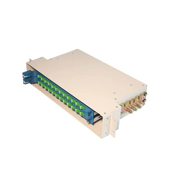
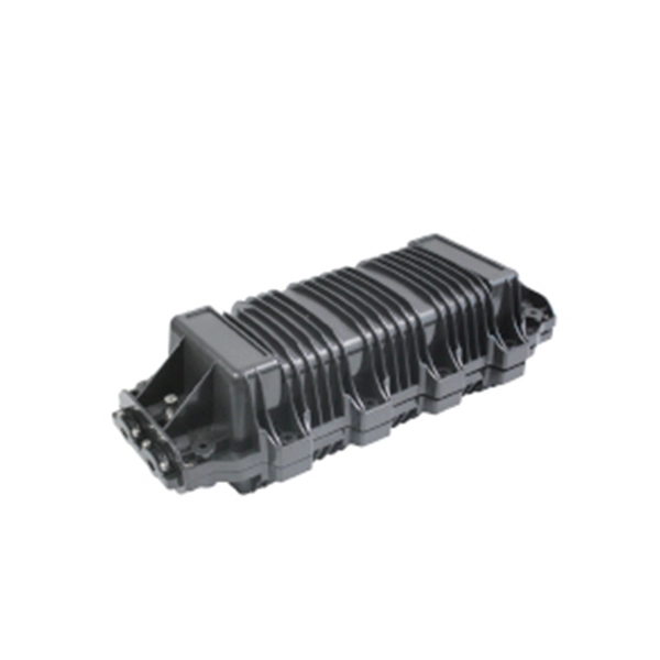
Product Features: Square protective box, suitable for skin cable and leather cable tight protection 6cm in length of skin heat shrink tube welding protection. A close connection between the leather cable and pigtail. Looking for specific info?. *In the era of high bandwidth, reliable fiber optic power equipment is particularly important. This handheld photometer can help check cable performance, calculate relative power loss, locate faults, and troubleshoot. *Measure the length of network cables, coaxial cables, and telephone cables. Able. Usually ships within 3 to 4 weeks Click here for details of availability. Able to test open, short, cross-connect, See more product details TABKER 4000667180167 3 x 2 x 1. Check each product page for other buying options. Price and other details may vary based on product size and color. Need help?. power across any given fiber. This document will serve as an overview of the major features and functions of the device and will ofer tips for trouble shooting com on issues in optical networks. If you are looking for a low cost device capable of saving and reporting take a look at the RP460 or. ments to the instrument's performance and functionality. The figures given in this manual ion of this manual to ensure the accuracy of its contents. However, should you have any questions or fi gistered users with a variety of information and services. Please allow us to serve you best by.
[PDF]
Versions designed for PDU power distribution purposes in data centers and server room applications. In this Suriname project, the client needed exactly that kind of logic: a power-distribution structure that separated critical loads, supported safe protection, and made long-term plant management easier rather than more complicated. The Suriname bottling plant required a centralized low-voltage. The Republic of Suriname has received financing in the amount of USD 105,695,000. 00 (One Hundred Five Million and Six Hundred Ninety Five Thousand United States Dollar) from the Islamic Development Bank (IsDB) Group and the Saudi Fund for Development (SFD) toward the cost of the Expansion of. right Castalia Limit d. Castalia is not liable for any loss caused by re ance on this document. Multiple outlet power strips are manufactured in accordance to Suriname standards with agency approvals. Quality Suriname power strips, in stock, for standard duty applications up. Can't find the product you need? Please give us feedback Dongfeng-covering various types of distribution boxes_rich and diverse product system, covering various types of distribution boxes and cabinet products. the Procurement Guidelines. In addition, please refer to paragraphs 1. 5 setting forth IsDB's pol o at fundable fee of USD 500. The method of payment will be direct deposit to a specified account number which will be shared after we have recei ed the written application.
[PDF]

The core measurement procedure follows five steps: Turn on the meter and let it warm up. Most meters need a brief stabilization period before readings are reliable. Check your model's manual, but a minute or two is typical. Set the wavelength to match your light source. Fiber loss is the difference between the power when light is coupled from the transmitting end to the fiber and the power when the light reaches the receiving end. Generally speaking, when measuring the. An optical power meter measures the strength of light traveling through a fiber optic cable, giving you a reading in dBm (decibels relative to one milliwatt). The basic process is straightforward: turn the meter on, set it to the correct wavelength, clean your connectors, plug in, and read the. A power meter and light source are essential test tools that work in tandem to measure fiber optic cable loss and evaluate the quality of optical links. They provide the data necessary to quantify signal loss and pinpoint issues that could impact network performance. Here's how they work: A power. You measure optical power in dBm or insertion loss in dB. Verify light travels from transmitter to receiver. We'll give you the basic information you need and provide some printable references.
[PDF]

Communication networks are an integral part of interconnected transmission lines in a power grid, analogous to the spinal cord for control signal and information exchange among substations, data hubs, and load dispatch centers. This article cov. Communication networks are an integral part of interconnected transmission lines in a power grid, analogous to the spinal cord for control signal and information exchange among substations, data hubs, and load dispatch centers. This article covers the major trend and design aspects of fiber optics communication link in power transmission line netwo. The communication network in the power grid is one of the most interrelated systems that require perfect compliance in equipment and protocol selection. While the high voltage components are relatively unchanged over decades in terms of operating principles, the communication protocols and equipment are seeing astonishing advancements every year. S. 2.1 Knowhow of prevailing setupWhile the primary objective is always to get the best solution for the lowest price, in the case of extension projects, the design engineers must also keep an eye on the existing setup. The issue of back-compatibility and upgradationsshould be properly accessed in existing equipment, even more so in the case of proprietary legacy setups. Figure below illustrates one such group of communication equipment in existing substations that might need proper interfacing and compatibility adapters befo.
[PDF]

There are many types of protective relays, and each one is designed for a specific type of protection. Common types include overcurrent relay, differential relay, distance relay, earth fault relay, and under/over voltage relay. Protective Relay Definition: A protective relay is an automatic device that senses abnormal conditions in electrical circuits and triggers actions to isolate faults. HT panel protection relay. The HT power supply is received from GO switch and distributed to the. Provides protection, logic, and metering All-in-one solution. Combines protection, sensors, control power, and circuit breaker in a single package Typically added to a breaker close circuit to prevent accidental reclosure after a trip. Three fundamental components required for each circuit breaker. Its main purpose is to safeguard electrical equipment like transformers, generators, and transmission lines from damage due to. There are different types of relays available and each type is used based on the requirement. So this article discusses an overview of a protective relay or protection relay – working with applications.
[PDF]
Microprocessor-based solid-state digital protection relays now emulate the original devices, as well as providing types of protection and supervision impractical with electromechanical relays.OverviewIn, a protective relay is a device designed to trip a when a is detected. The first protective relays were electromagnetic devices, relying on coils operating on moving par. Electromechanical protective relays operate by either, or. Unlike switching type electromechanical with fixed and usually ill-defined operating voltage thresholds. Electromechanical relays can be classified into several different types as follows: "Armature"-type relays have a pivoted lever supported on a hinge or knife-edge pivot, which carries a moving contact. These relays may.
[PDF]

The K factor (or zero-sequence compensation factor) adjusts the measured impedance for the phase-to-ground fault loop by accounting for the contribution of zero-sequence currents. This compensation is critical because zero-sequence current introduces an offset in the fault impedance. The following Terms are used in protective relaying: 1. Fault Clearing Time 5. Drop Out or Reset value 8. Sealing Relay or holding Relay 10. Hermetically sealed, corrosion resistant metal can. Detail specifications and ordering data appear on the Data Sheet below. NewElec's KA, KB & KC Series relays provide robust and dependable motor protection relays designed to safeguard critical motors in a wide range of industrial applications. Fixed thermal curves (Class 15 Cold - Class 5 Hot) with thermal pre-loading, match the Hot and Cold stall times of the motor during operation. The KA relay is mains powered. The protection and control devices in electrical equipment can be referred to by numbers, with appropriate suffix letters when necessary, according to the functions they perform. These numbers are based on a system that is adopted by a standard for automatic switchgear by Institute of Electrical.
[PDF]

PC configuration software for Reyrolle products including Reydisp Manager 2, Reydisp Manager 1, and Reydisp Evolution. Doble RTS™ (RTS) is the premier protection testing software system for improving the work of testing relays and managing test records. Process consistency with power and flexibility set RTS software apart, and tremendous automation enables unmatched efficiency, accuracy and productivity. Apply your. Download documents, support information, software, video and audio content. IEC61850 Digital Substation Testing With 15 years experience in IEC61850 digital substation testing, KINGSINE portable relay testers are designed for comprehensive testing in both traditional and digital substations, including MU and IEC61850 compliant IEDs. Protection Relay Test Set/Kit KINGSINE. The commissioning of protection systems is an essential step to ensure the safety, reliability, and operational efficiency of electrical installations. In this context, the testing of protection relays and IEDs (Intelligent Electronic Devices) must be carried out with maximum precision, speed, and. A software designed to manage all aspects of protective relay testing using the Megger SMRT and FREJA models of relay testers. Facilitates steamlined and efficient relay protection testing through automation and relay modules. By using one of the over 400 relay templates with relay settings import. Portable at just 15 kg, the FREJA 300 is intended primarily for.
[PDF]
In, a protective relay is a device designed to trip a when a is detected. The first protective relays were electromagnetic devices, relying on coils operating on moving parts to provide detection of abnormal operating conditions such as over-current,, reverse flow, over-frequency, and under-frequency.
[PDF]

The modern electric power transmission, control, and distribution network demands precision, reliability, and advanced data analytics for each step in its operation. As a Relay Protection Engineer, your work in relay testing and commissioning is critical to ensuring system safety and continuity. In. The testing and verification of protection devices and arrangements introduces a number of issues. This happens because the main function of protection devices is related to operation under fault conditions so these devices cannot be tested under normal operating conditions. Protection relays are critical for detecting faults, initiating protective actions, and isolating faulty sections of the. Relay systems protect high-voltage equipment and transmission lines to ensure safe, stable systems. Although failure of a protective relay system may have severe local or regional impacts, most protective relay systems are not required to operate to prove they are in working order. Ensuring that. The strategies available to remove these risks are many, but all involve some kind of testing at site. Modern power systems are becoming increasingly complex, with growing demand, integration of renewable energy, and rising expectations for reliability and safety. In this environment, protection relays serve as the guardians of.
[PDF]
Electromechanical protective relays at a hydroelectric generating plant. The relays are in round glass cases. The rectangular devices are test connection blocks, used for testing and isolation of instrument transformer circuits.OverviewIn, a protective relay is a device designed to trip a when a is detected. The first protective relays were electromagnetic devices, relying on coils operating on moving par. Electromechanical protective relays operate by either, or. Unlike switching type electromechanical with fixed and usually ill-defined operating voltage thresholds. Electromechanical relays can be classified into several different types as follows: "Armature"-type relays have a pivoted lever supported on a hinge or knife-edge pivot, which carries a moving contact. These relays may.
[PDF]
Electric power distribution systems are designed to serve their customers with reliable and high-quality power. The most common distribution system consists of simple radial circuits (feeders) that can be ove.
[PDF]

This standard covers the construction, mechanical, electrical, and optical performance, installation guidelines, acceptance criteria, test requirements, environmental considerations, and accessories for a nonmetallic, all-dielectric self-supporting (ADSS) fiber optic cable. An All-Dielectric Self-Supporting (ADSS) cable operates without metallic messengers, relying entirely on its aramid yarn strength members. For a typical 12-fiber ADSS cable with a 8. AFL-ADSS® (All-Dielectric Self-Supporting) cable is ideal for installation in distribution as well as transmission environments. This guide provides general recommendations for the selection of methods, equipment, and tools for the stringing of ADSS (All Dielectric Self-upporting) fiber optic cables including short and Long Span ADSS cables. The installation methods for ADSS cables are essentially the same as those used for. This Installation Manual is a recommendatory installation document provided by HANGZHOU ZION COMMUNICATION CO. The installation manual is established based on the newest issued international standards such as lEEE Std 1222: 2004, "lEEE standard for all-dielectric. Round aramid reinforced ADSS cable for intermediate and long spans, 4 – 96 fibres. VDE: A- DF 2Y (ZN) 2Y This specification covers a family of optical cables with 4 - 96 fibres for intermediate and long spans.
[PDF]
The distribution box is divided into power distribution box and lighting distribution box, which is the final equipment of the power distribution system. Both are strong electricity. The distribution box is a low-voltage power distribution device that assembles switchgear. A panelboard is a component of an electrical distribution system which divides an electrical power feed into branch circuits, while providing a protective circuit breaker or fuse for each circuit, in a common enclosure. A panelboard services to protect branch circuits from overloads and short. The distribution box is an electrical equipment with the characteristics of small size, easy installation, special technical performance, fixed position, unique configuration function, no site restrictions, widespread application, stable and reliable operation, high space utilization rate, small. A distribution box is according to the electrical wiring requirements of the switchgear, measuring instruments, protection appliances, and auxiliary equipment assembled in the enclosed or semi-enclosed metal cabinet or screen width, constituting a low-voltage power distribution device.
[PDF]

Electricity enters the box via the main breaker from the utility or generator. Power is passed to bus bars and adjusted to usable voltages (e. Breakers direct power to each circuit and trip during overloads. Neutral returns current; ground directs stray. A power distribution box (DB box) works by serving as a central electrical panel where electrical power is received and distributed from one input source to multiple output sources. This distribution box ensures the safe distribution of power throughout a building or area. Through its design and. A switchboard is a component of an electrical distribution system which divides an electrical power feed into branch circuits while providing a protective circuit breaker or fuse for each circuit in a common enclosure. Switchboards typically have a maximum voltage rating of 600 Vac/Vdc and a. A distribution box is a key part of electrical systems in buildings. Inside, you'll find parts like circuit breakers and fuses that protect the system from problems like overloads and short circuits. It ensures that electricity flows. Breakers are switches that turn off automatically when there's too much electricity or a short circuit. This helps prevent fires or damage. Without it, your devices and appliances could be in. Electrical switchboards are fundamental in controlling and distributing electricity in homes, offices, and industrial settings.
[PDF]