This guide will walk you through the process of checking photo sensors using a multimeter, covering various types of photo sensors, the necessary tools and safety precautions, and the specific measurement techniques involved. Knowing how to effectively use a multimeter to test photo sensors can save you time, money, and frustration when dealing with malfunctioning devices. more What is a Voltage Divider? | What is a Voltage. Before replacing the sensor or fixture, it's efficient testing it first, With a few tools and a step-by-step process you can find whether your outdoor lighting control system is working as intended or if the problem lies elsewhere. In this complete guide from Lead-Top, a global leader in photocell. In this blog post, we explain step-by-step how to troubleshoot a sensor with a digital multimeter (DMM). Here are the steps: Troubleshooting a sensor measurement failure requires mechanical tools to uncover the protective shields or components so you can reach the sensor in question. Always follow the manufacturer's instructions for the sensor and multimeter. Ensure the sensor is properly connected to the multimeter and. A multimeter is an indispensable diagnostic tool for anyone working with electronics, electrical systems, or indeed, sensors. It's a versatile device capable of measuring voltage, current, and resistance, providing crucial insights into the health and functionality of electrical circuits and.
[PDF]

In this case use an optical power meter (OPM) and test the input port of the splitter for the optical power level (dBm) from the OLT at 1490 nm. If there is no or reduced power then the patchcord or OLT is the culprit. If the power level is reduced it could be as simple as a. So for this simple 1X2 splitter, how do we test it? Simply follow the same directions for a double-ended loss test. Attach a launch reference cable to the test source of the proper wavelength (some splitters are wavelength dependent), calibrate the output of the launch cable with the meter to set. Optical splitters in the outside plant (OSP) are used mostly in passive optical networks (PONs) for fiber-to-the-user (FTTx) networks, and are often overlooked as failure points. In this article I focus on a few basics of optical splitters, their applications, typical causes of failures, and how to. Now, we test the simplest 1x2 optical splitter as the picture shown below. 001 dB), OTDR (for reflection event detection). Cleaning tools. The CertiFiber® Pro Optical Loss Test Set (OLTS) can be used to check that the loss of a PON Splitter (often referred to in various standards as a non-wavelength-selective or wavelength-selective branching device) to check that it is within the allowed defined limits. The CertiFiber® Pro has an.
[PDF]

The socket accepts laser diodes with wire leads 24 to 26 gauge, 0. The maximum recommended current is 3 Amps. Specifications: Outside dimensions: 0. Thorlabs offers a versatile range of accessories for convenient integration of laser diodes into functional systems. These laser diode sockets are ideal for OEM-type implementations and are compatible with our selection of Ø3. 6 mm, Ø9 mm, and TO-5 laser diode packages. All of these sockets. Wide Range of Standard Products and Flexible Customization We offer a variety of standard products with different pitches, pin counts, and pin arrangements, helping to shorten lead times. Compatible with TO-18, TO-46, TO-52, TO-72, and more (please refer to the lineup at the bottom of the page for. Pricing (USD) Filter the results in the table by unit price based on your quantity. A tariff of 8% may be applied if shipping to the United States. A. Compact miniature socket size for maximum board density Accomodates most any TO package format with pin circle options of. The S8060 and S8060-4 sockets have a polarization dot on the top of. 4-Pins Laser Diode Test Socket High Precision Diode Test Stand 1. The inner hole of the pin is a through hole, and the length of the laser diode to be tested can be universal. The pins are made of gold-plated copper tubes, low resistance, not easy to oxidize, long service life.
[PDF]

Regularly testing fiber optic cables helps minimize network downtime, lengthens the network's longevity, reduces maintenance requirements, and helps support network reconfiguration and upgrades. Fiber optic testing ensures the performance and reliability of fiber optic networks. Key tests include: Effective fiber testing utilizes advanced tools such as Optical. Fiber optic testing for continuity is crucial in ensuring that light transmits through fiber optic cables without interruptions, safeguarding seamless data transmission. This guide talks about the primary methods and tools for effective continuity testing in fiber optic cable networks. Insertion loss testing confirms whether the cable meets design loss budgets. OTDR testing identifies events along the fiber length, including: OTDR is essential for long-distance FTTH feeder and distribution cables. After the cables are installed and terminated, it's time for testing. For every fiber optic cable plant, you will need to test for continuity, end-to-end loss and then troubleshoot the problems. If it's a long outside plant cable with intermediate splices, you will probably want to verify the. We'll explain why it's vital to test fiber optic cables, the three most popular methods, and when you should use them. Why Testing Fiber Optic Cables Matters? Regular testing of fiber optic cables is not just a preventive measure; it's an.
[PDF]

The fastest way to test a fluorescent tube is with a multimeter set to continuity mode. Each end of the tube has two pins connected by a thin filament inside the glass. If either filament is broken, the tube is dead. The whole test takes about 30 seconds per tube once you know what. This is a complete guide for testing a fluorescent light bulb with a multimeter. You don't have to be an expert in electrical work. This process measures electrical resistance to determine if the tube has suffered an internal failure before replacing the bulb or investigating the ballast. This guide provides a comprehensive understanding of the process, equipping you with the knowledge and. To test a fluorescent light bulb, observe any of the following: flickering light, low brightness, buzzing sound, delayed start, and fading color and light variation. Turn off the power to the circuit that powers the fixture and keep the leads steady to ensure accurate readings. Multimeters provide. How to Test Light Bulbs & Fluorescent Tubes with a Multimeter (Continuity Check) Is your lamp or fixture failing to light up? Before you buy a new bulb, you need to confirm if the bulb or tube itself is the problem! A simple continuity check using a multimeter can instantly tell you if the filament.
[PDF]

Fiber optic connector pull test demonstration with real-time insertion loss monitoring. We use an optical loss tester to track signal stability every second while controlled tension is applied to the fiber. more. Fiber optic cable is surprisingly strong, durable and pliable; however, several best practices should be followed to ensure a successful cable installation. The below article explores the best practices and tools commonly used to pull fiber optic cable. The Future Ready Solutions Tools & Test. NEOFIBO TFTM-100N Vertical Fiber Optics Cable Tension Testing Machine The Cable Tensile Testing Machine is a precision mechanical measuring instrument designed to evaluate the tensile strength and elongation properties of various cables, wires, and fiber optic assemblies. Most fiber damage does not come from normal operation after the system is live. It happens during installation, when excessive pulling force, tight bends. Fiber optic connectors are designed to be connected and disconnected many times without affecting the optical performance of the fiber circuit. Optimal performance can be achieved by following the correct process for termination of the fiber circuit—a task which requires the use of a wide range of. The Fluke Networks JR-LEV-1 JackRapid Punch Down Tool is a cable termination tool that is designed to give technicians maximal efficiency in cable maintenance.
[PDF]

BER is calculated by comparing the transmitted sequence of bits to the received bits and then counting the number of errors. Whether you're a network engineer validating new inventory or an integrator preparing for deployment, knowing how to test optical transceiver modules can save time, reduce failures, and ensure SLA compliance. Unchecked optical modules can cause: Testing ensures compliance with IEEE 802. 3 and MSA. Bit Error Rate (BER) is a measure of telecommunication signal integrity based on the quantity or percentage of transmitted bits that are received incorrectly. Essentially, the more incorrect bits, the greater the impact on signal quality. It is defined as the ratio of the number of bits received in error to the total number of bits transmitted. It quantifies the error frequency caused by disturbances like statistical noise. What causes bit errors in optical data transmission? In optical systems, bit errors are. One of the most important ways to determine the quality of a digital transmission system is to measure its Bit Error Ratio (BER). Through the interpretation of actual test reports, it.
[PDF]

The PV combiner box test in solar power systems is a fundamental procedure that verifies the accuracy of string connections and the electrical current flowing to inverters. This test helps prevent energy losses while optimizing system performance. ance cables by combining strings at the array locat ciency, reliability and safety in solar energy systems. They enable centralized management in large-scale and remote installation ity), equipment aging, and poor installation practices. MapperX performs this critical test professionally. This guide provides a step-by-step method for safely testing energized PV strings to locate intermittent ground faults using reliable tools and procedures. What Is an Intermittent Ground Fault? An intermittent ground fault is a temporary electrical connection between a current-carrying conductor. A PV combiner box, often referred to as a solar combiner box, is a critical component in solar energy systems. This device plays a significant role in both residential and commercial solar installations, particularly when. We do a lot of solar PV and renewable energy asset inspections here at HelioVolta and SolarGrade! Every time we visit a site, we use the SolarGrade platform to guide our workflow and document our findings. Missing/Improper Label Improper labeling can be a risk to personnel and should conform to.
[PDF]
Fiber testing is the process of verifying the performance of optical fiber cabling. This process includes a range of tests and measurements such as insertion loss, optical return loss, and fiber length. It encompass.
[PDF]
This standard outlines the construction requirements, testing methods, and performance parameters for cable trays and related support systems. As one of the best Cable Tray Manufacturers in Madagascar, we are trusted by people not only within the boundaries but even beyond that. Our custom-based products are able to match up your distinct needs. Whether you're designing a new facility or upgrading an existing electrical infrastructure, understanding and applying the IEC standard for cable tray is. us-trations without notice. All illustrations, descriptions and technical information included in this document are provided as indications and can cable trays are equivalent. The mechanical and electrical characteristics, tests, certifications, overall quality management, recommendations mentioned. Not all cable trays are equivalent. IEC 61537 covers cable tray and cable ladder systems for the support and accommodation of cables, while NEC Article 392 governs cable. We, one of the well-known Cable Trays Manufacturers in Madagascar, offer top-notch trays that keep your electrical system organized and protected. Our durable, high-quality trays come in various sizes and styles to fit any project, big or small. Our robust trays safeguard your cables from physical.
[PDF]
Fiber optic connectors are the backbone of high-speed data transmission, but choosing the right interface—SC, LC, or MPO—can make or break your network's efficiency. In this head-to-head comparison, we analyze their size, port density, performance metrics, and ideal use cases, backed by data charts. They use precision ferrules and alignment sleeves to connect two fiber cores, maintaining light transmission efficiency. Because of this, it's no surprise that fiber optic connectors are in high demand across several industries. Their primary function is to precisely align the end faces of two optical fibers via an intricate mechanical structure to minimize optical signal transmission loss. The basic structure includes components such as. Fiber optic connectors are essential components in optical communication systems, enabling quick and stable connections between fibers. They are. LC, SC, FC, ST, MPO/MTP compared: ferrule sizes, polishing types, insertion loss, and a decision flowchart to choose the right fiber connector for your application. This allows for quickly connecting and disconnecting of fiber optic cables without splicing. The connector features a ferrule, the connector end piece that holds and secures the fiber and aligns it for light.
[PDF]
With the large variety of beamsplitters available, the designer needs to take many factors into consideration. This article and its illustrations will go a long way toward making the correct choice less of a risk. All curves show typical performance. A beam splitter (or beamsplitter, power splitter) is an optical device which can split an incident light beam (e. a laser beam) into two (or sometimes more) beams, which may or may not have the same optical power (radiant flux). It is a crucial part of many optical experimental and measurement systems, such as interferometers, also finding widespread application in fibre optic telecommunications. One beam is typically reflected while the other is transmitted. Beamsplitters are often classified according to their construction: cube or plate. In this blog, we will explore the step-by-step process of using a beamsplitter cube effectively, along with some common applications that benefit from this powerful optical tool. Step-by-Step Guide on Using a Beamsplitter Cube Step 1: Understanding the Cube Orientation: A beamsplitter cube is a. A beam splitter is an optical device that splits beams (such as laser beams) into two (or more) beams. Beam splitters typically come in the form of a reflective device that can split beams into exactly 50/50, half of the beam being transmitted through the splitter and half being reflected.
[PDF]

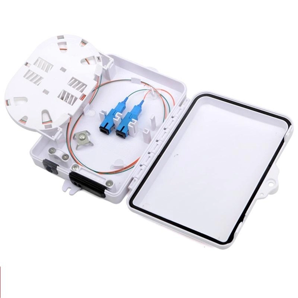
If you are ever in need of checking your ONT, this video will show you how to do so and what it is you are looking for. Always remember to securely close the box afterwards to prevent any damage to the facilities inside. more. A fiber termination box is the standard instrument used in fiber optic networks to connect, secure, and protect optical fibers at the terminating point. It functions as a junction between the incoming fiber cable and the outgoing customer-side fiber cable, where one fiber can be spliced, patched. Open the Fiber optic terminal box. Check and prepare installation tools and accessories. Prepare the cable according to the design. An ONT, or Optical Network Terminal, is the box where your fiber internet connection enters your home to power your fiber network. Your ONT is typically located in your garage, basement or outside your home within a few feet of your home's power box. It serves as a termination point for optical fibers, providing a secure and organized space for connecting and managing fiber optic cables. A fiber pigtail is a specific hardware connection used for cable termination. Proper installation and maintenance of FTBs are essential to ensure the reliability and performance of the network infrastructure.
[PDF]
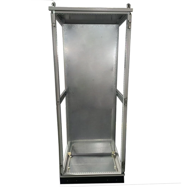
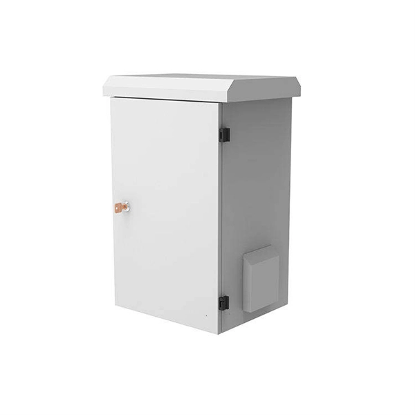
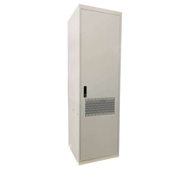
The XL type low-voltage power distribution cabinet uses domestically designed new components. The enclosure is made of bent steel plates, featuring a compact structure, easy maintenance, and flexible circuit scheme combinations. The 19-inch rack-mounted end box is a passive component for terminal distribution of trunk cables in fiber-optic communication systems, with tools for easy connection and distribution of fiber optic circuits. Sopto offers 19 Inch Rack Drawer Distribution box (Fiber Patch Panel) and 19 Inch Rack. 2 Core Fiber Optic Distribution Indoor Box (wall mount box type) © 2024 E-Talk Maldives. Nuomak is proud to announce a new cooperation with a client in the Maldives, for whom we have manufactured PS cabinets, MCCBs, and transparent waterproof electrical distribution boxes. These products are specially designed to meet the challenges of high humidity, salt spray, and harsh coastal. Need assistance? Let us help you with your questions and queries. Send a message to Viber: 7317894 Promotions, new products and sales. Directly to your inbox. Besides air circuit breakers and fuses for circuit protection, the. The electrical enclosure is made of wear-resistant and rust-resistant stainless steel, which can be widely used in indoor and outdoor applications, such as power, construction and other industries; allowing your equipment to be well protected in harsh environments. · Easy installation and easy.
[PDF]
Wall-mounted fiber distribution frames are typically designed as box-like structures, ideal for locations with fewer cables and fiber cores. Whether you're building a central office, data center, or FTTx distribution network, understanding the right ODF. FDF, or Fiber Distribution Frame, is a key component used for the termination, utilization, and management of optical cables between wiring rooms and equipment rooms. In structured cabling systems, ODFs are suitable for horizontal cabling between equipment or their terminations, as well as. A distribution boxes is an essential device that manages the safe and efficient flow of electrical power throughout different areas of a building or facility. It is commonly used in homes, offices, and industrial settings to control and protect electrical circuits. Understand its role in electrical systems and safety.
[PDF]