
Optical fibers or fiber cables can be used for transmitting optical power from a source to some application. In their served areas will be power generating stations, alternative energy sources (solar, wind, geotherman, etc. ), substations for distribution and microgrids. These networks must be monitored and managed to ensure reliable power for the utility's customers. For monitoring and managing networks. Low voltage cables are mounted on poles in the "telecom space," well below power cables. Optical power ground wire (OPGW) is an electrical power ground with fiber optics in the center of the conductor. That conversion can be done with a photovoltaic cell. The Commission, on June 22, 1965, noting that the increasing demand for underground electric and communication facilities in California has brought about substantial increases in the construction of such facilities, and that it appeared it may be desirable, pursuant to Sections 761, 768 and 8056 of. One choice is optical power ground wire (OPGW). This conductive cable is run at the top of the tower or pole to be the ground conductor and protect the power cables from lightning. The fiber. While fiber optics is essential for internet service providers to deliver higher bandwidth and faster transmit speeds, there are also many crucial benefits of fiber optics in energy and power. Utility companies face various challenges as they work to deliver reliable energy to homes and industries.
[PDF]

Instead of relying on assumptions, this guide offers a clear-eyed look at how to properly secure your fiber infrastructure, moving beyond the myths to implement practical, layered defenses that provide real-world protection for your organization's most sensitive data. For manufacturers and industry professionals involved in creating, deploying, or maintaining these critical systems, ensuring the robust and reliable securement of fiber optic cables is paramount. “Securing” fiber optic cable goes beyond just preventing it from moving; it encompasses protecting its. Fiber optic cables enable high-speed, long-distance data transfer, forming the backbone of modern communication. Yet, outdoors, they face temperature swings, moisture, UV exposure, rodents, and human interference. Protecting them is essential for long-term reliability. This guide covers how to. Fiber optic and ACSR (Aluminum Conductor Steel Reinforced) cables play a critical role in modern infrastructure, including power transmission and telecommunications. However, these cables face several challenges that can compromise their performance and longevity. If you are an optical engineer or a fiber optic network operator, you need to know how to protect your cables from these threats and ensure. An effective fiber optic network security plan acknowledges these potential weak spots and addresses them head-on. Before beginning any installation, safety.
[PDF]

In this video, we'll walk you through the process of resurrecting y. The test sets display a laser warning icon when the laser source is active to alert the user about a potentially dangerous situation. It is recommended to: Deactivate the laser before connecting or disconnecting optical cables or patchcords. more Is your optical power meter showing no signs of life? Don't worry; we've got you covered! In. Introduction The RP460 Optical Power Meter is an ultra low cost, and compact power meter used for verifying both absolute and relative power across any given fiber. This document will serve as an overview of the major features and functions of the device and will offer tips for trouble shooting. Fiber Optical Powermeter User Manual | FS Title Author Subject Keywords Created Date. The OPM1315 is a newly developed portable optical power meter. It is equipped with a 1. 0 mm large area detector so that stability and reliability can be enhanced effectively. This unit is designed to fit the hand comfortably, and can be used for installation, debugging, and maintenance of any fiber. ments to the instrument's performance and functionality. The figures given in this manual ion of this manual to ensure the accuracy of its contents. However, should you have any questions or fi gistered users with a variety of information and services. Please allow us to serve you best by.
[PDF]

It consists of 5 buttons. A power button, a button to turn on the VFL, a lambda button to set the wavelendth, a REF button, and a dBm/W button to set the unit of power. First, you check the initial power of a light signal. Then you check its power at the other end of optical. OPM interface: insert the fiber to be tested, test the optical power. REF/dB key: Short press the dB to switch unit, click once nW/dBm/dB to enter the upper clear data, press and hold until REF is displayed on the screen, and set the current optical power as reference value, enter the relative. There are two buttons on this meter. One is the power button, used to turn the meter on/off. At the top, there is a sensor that detects the light beam. The. at -22 (or 25 with tone on)). To do this you. Active Equipment Power Measurement Fiber Continuity Patch Cable Testing Check MM Reference Cables - Dual OWL MM Sources Check MM Reference Cables - WaveSource MM Sources Check SM Reference Cables - Laser OWL SM Sources Check SM Reference Cables - WaveSource SM Sources. Power-off: Press and hold “MODE” key for 2 seconds or more until “OFF” displays on the screen. Note: This instrument will shut down automatically without receiving any operation instruction for 10 minutes. Function selections: It.
[PDF]

The core measurement procedure follows five steps: Turn on the meter and let it warm up. Most meters need a brief stabilization period before readings are reliable. Check your model's manual, but a minute or two is typical. Set the wavelength to match your light source. Fiber loss is the difference between the power when light is coupled from the transmitting end to the fiber and the power when the light reaches the receiving end. Generally speaking, when measuring the. An optical power meter measures the strength of light traveling through a fiber optic cable, giving you a reading in dBm (decibels relative to one milliwatt). The basic process is straightforward: turn the meter on, set it to the correct wavelength, clean your connectors, plug in, and read the. A power meter and light source are essential test tools that work in tandem to measure fiber optic cable loss and evaluate the quality of optical links. They provide the data necessary to quantify signal loss and pinpoint issues that could impact network performance. Here's how they work: A power. You measure optical power in dBm or insertion loss in dB. Verify light travels from transmitter to receiver. We'll give you the basic information you need and provide some printable references.
[PDF]

How to Use Optical Power Meter TR-504 | Optical Power Meter Working| Testing OPM, VFL, RJ45 | TRICOM In this video, we walk you through how to use the TRICOM TR-504 Optical Power Meter and explain how it works. Learn how to test fiber optic cables, OPM, VFL . Optical power meters are a key element in the optimization and maintenance of such optical networks and of their components. In this article, learn: What is an optical power meter? An optical power meter (OPM) measures the power levels of light signals in devices that transmit data or power using. An optical power meter measures the strength of light traveling through a fiber optic cable, giving you a reading in dBm (decibels relative to one milliwatt). The basic process is straightforward: turn the meter on, set it to the correct wavelength, clean your connectors, plug in, and read the. OPM interface: insert the fiber to be tested, test the optical power. An optical power meter is a tool that measures the number of optical power in a cable is fiber-optic. It helps engineers verify the performance of optical fiber systems, ensuring that the signal strength meets requirements, and is an essential tool for communication network maintenance and troubleshooting.
[PDF]

In this video im showing and explaining how to climb a power pole using a fall protection belt, also drilling into a pole and framing it for 1/4 strand that will supports the fiber optic cable. more. Deploying fiber above ground on poles or towers removes the need for underground digging and is particularly useful when the ground is uneven, rocky or both. Aerial installation is generally much less costly than underground construction also. Fiber in a duct solutions have a major aesthetic. The Fiber Optic Association, Inc. (FOA) was founded in 1995 to help develop the workforce to build the fiber optic networks to support a rapid expansion in communications and the Internet. This lesson covers the installation of poles and. ADSS (All Dielectric Self Supported fibre optic cables) OPGW (Optical Ground Wire) The installation methods for fibre optic cables are largely the same as those with conventional copper cables. These may be considerably different from those of the copper cable. When installed correctly, ADSS cables can last more than 25 years, providing stable, high-speed communication even in difficult outdoor environments. But to get the best.
[PDF]

The OPM 510 and 520 are available in standard and high-power versions for the Telco and MSO markets. The OPM510 and OPM520 supports wavelengths of 850, 980, 1270 1300, 1310, 1490, 1550, 1577, 1623 and 1650nm. The rugged enclosure provides confidence when testing singlemode and. Count on Tempo Communications Optical Power Meters (OPM510/520) to test and maintain your fiber optic networks. Our optical power meters feature built-in calibration factors. Optical power meters and detectors have been served by Newport for over 30 years. The offering ranges from a low cost, hand-held meter to the most advanced dual channel benchtop power meter available in the market. Our 1936-R/2936-R series boasts state-of-the-art analog boards with a whopping 250. © Copyright© Santec Holdings Corporation. Demo the full range, from multi-use to dedicated PON and FTTH. VIAVI offers fast, cost-effective, and easy-to-use power meters for installation and maintenance of single mode and multimode fiber optic networks and. AFL is a trusted supplier of optical testing equipment with more than 30 years of experience and tens of thousands of units in use in the field. AFL's full range of power meters are used for testing single-mode and/or multimode fiber networks. Power meters with wave ID can detect two or more.
[PDF]

Here's a comprehensive guide to the 15 best optical power meters for fiber techs in 2025, offering expert insights and reviews to help you find the perfect tool for your needs. Also, please take a look at the list of 26 optical power meter manufacturers and their company rankings. Novanta Photonics, 3. What Is an Optical Power Meter? What Is an Optical Power Meter? An optical. | | | | | |. Optical power meters measure the average optical power (energy per unit time) of continuous-wave (CW) or high-repetition-rate pulsed light sources. They are distinct from optical energy meters, which measure the energy of single light pulses, although some consoles support both sensor types. They. Optical power meters and detectors have been served by Newport for over 30 years. The offering ranges from a low cost, hand-held meter to the most advanced dual channel benchtop power meter available in the market. Our 1936-R/2936-R series boasts state-of-the-art analog boards with a whopping 250. HPC-50BVhandheld optical power meter has compactsize and high reliability. It can make accurate measurement on seven operating wavelengths (850/980/1300/1310/1490/1550 /1625nm). ST800K-UC SC/ST/FC Li battery with USB, -70~+10 dbm optical power meter. Optical Power Meters from ADC Corporation are listed on GoPhotonics. Use the filters to.
[PDF]

A 4 Core Optical Cable is a fiber optic cable that contains four individual optical fibers within a single protective outer jacket. Each fiber is capable of independent data transmission. A TOSLINK optical fiber cable with a clear jacket. These cables are used mainly for digital audio connections between devices. A fiber-optic cable, also known as an optical-fiber cable, is an assembly similar to an electrical cable but containing one or more optical fibers that are used to carry. This guide covers everything you need to know about 4 core fiber, including its internal structure, TIA standard color coding, and how to choose the right type. They are ideal for long-distance communication and. But generally, the cable core, strength member and outer sheath together make a fiber optic cable. It transmits electricity or information from one place to another. These fibers are used to transmit data as light signals, offering high-speed data transfer capabilities over long distances with minimal loss. Fiber optic cables are crucial.
[PDF]

In short length cables a visual fault locator (VFL) can find where the cut is or find the bad connector at patch panels. For longer distance cables, the use of an OTDR is required. Once the fault is located, fusion splicers and splice-on connectors can be used to complete the repair. Fiber optic cables are the backbone of modern networks, delivering fast and reliable data transmission. Accidental cuts, breaks, or other damage can disrupt your network and cause costly downtime. With the right tools and techniques, you can efficiently repair damaged fiber cables and restore. Fiber optics offers advantages like EMI immunity and low attenuation (0. 2 dB/km), but it's fragile—susceptible to breaks, bends, and contamination. Repairs focus on restoring the light path with minimal signal loss (<0. A fusion. Visual inspection and specialized tools like OTDRs, OPMs, and VFLs are essential for identifying and locating physical damage or faults in fiber optic cables. Emergency restoration planning involves implementing backup power solutions, network redundancy planning, and strategies for prompt. Fiber optic cables are critical components of modern communication networks, transmitting vast amounts of data at lightning speeds.
[PDF]
Power consumption of fiber optic cables can range from 0. 01-100 W/Gbps depending on the length of the cable (chart below). To ensure that fiber-optic connections have sufficient power for correct operation, calculate the link's power budget when planning fiber-optic cable layout and distances. The power budget is. Attenuation is the difference between the launch power of the signal from the transmitter and the power of the signal at the receiver. Each. The power consumption of coherent fiber-optical communication systems is beco-ming increasingly important, for both environmental and economical reasons. The data traffic on the Internet is increasing at a faster pace than that at which optical network equipment is becoming more energy efficient. With the growing global deployment of Fiber-to-the-Home (FTTH) networks driven by the demand for ensuring high-capacity broadband services, mobile network operators (MNOs) face challenges of excessive energy consumption (EC) of wired optical access networks (OANs). You use power budget calculations to verify whether an optical link—FTTH, ODN, backbone, or data center—can operate reliably under all. Reduced power consumption: 800G optical devices can achieve energy savings at the optical and system level, such as using more efficient modulation formats, optimizing circuit design, and reducing power density.
[PDF]
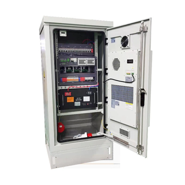
Designed without adapter slots, this enclosure provides a high-reliability, low-loss solution for environments where permanent fusion splicing is preferred over plug-and-play connections. It supports the functions of fusion splicing, optical signal splitting and fiber management. Fiber Optic Distribution Cabinet, short for FDC, is specially used for cross connect of fiber optic feeder cables and distribution cables in Fiber to the Home network. Fiber Optic. An optical distribution frame (ODF) is a frame used to provide cable interconnections between communication facilities, which can integrate fibre splicing, fibre termination, fibre optic adapters & connectors and cable connections together in a single unit. The "12C" signifies a 12-count configuration, indicating it can accommodate up to 12 fiber connections. This ODF comes pre-loaded with SC simplex. Check each product page for other buying options. Big space for managing pigtails or splitters. It is equipped with 12 SC adapters and can work in outdoor environments. Our fixed type Patch panel can be applied in the branch connection of optical fiber termination;19" standard structure, rack mounted; Available for the adapters installation of FC,SC,ST,LC. The patch panel body is made of cold rolled steel sheet. Fixed Type of Rack Mounted Standard Fiber Terminal.
[PDF]
This article provides all the essential information about retrofitting fiber optics—from different installation methods and optimal placement of connections to costs and funding opportunities. In this guide, I'll walk you through the step-by-step process of moving your fiber phone line seamlessly, ensuring uninterrupted communication during your relocation. Why Move Your Fiber Phone Line? Fiber-optic technology offers unparalleled speed and reliability over traditional (and now becoming. Is the fiber cable run to my house on the same day as my installation appointment? I noticed the fiber cable is still on top of my yard after my service has been installed. When will it get buried? Will the technician need to drill into the side of my home? What equipment will the technician be. Fibre optic cable relocation involves moving existing fibre optic installations to a new location. This process demands careful planning to maintain service continuity and optimal performance. Key elements include the fibre core, cladding, and protective outer layer. 1 How to Relocate Fiber. At the moment we have 4 network cabs which are sparsely populated. The plan is to move the 4 cabs into 2. com/ ! Products used in this video: Single mode Fiber optic cable with duplex LC connectors: https://www. Ethernet to Fiber Optic Converter:.
[PDF]

Here's what to consider: 1. Fiber Type Choose single-mode for long-distance transmission and multimode for shorter runs. Connector Compatibility Match the connector (LC, SC, ST, etc. ) with your equipment ports. Fiber Count Select based on network scale—higher. Executive Summary: A fiber optic pigtail is one of the most commonly specified yet least understood components in structured cabling. Get the wrong connector type, the wrong polish, or skip proper fusion splicing technique—and you're looking at elevated signal loss, increased back reflection, and a. Today, I'll show you how to pick the right patch cord or pigtail — step by step. You plug it into a switch, router, or patch panel. A pigtail is for splicing. You fuse it to a. A fiber pigtail is a single, short, usually tight-buffered fiber optic cable with a factory-installed connector on one end, and un-terminated fiber on the other end. Fiber optic pigtails are used to terminated fiber optic cables via fusion splicing or mechanical splicing as shown in the picture. In this guide, we'll break down what fiber optic pigtails are, how they work, their types, and how to choose the right one for your application. By the end, you will have a comprehensive understanding of why pigtails deserve a place in every fiber deployment toolkit. Each type has its own unique design, size, and compatibility features. Understanding these differences is essential for choosing the right pigtail for your network.
[PDF]