A novel method for aligning multi-core fibers (MCF) provides a systematic approach for MCF splicing in the lab, in cable factories, and in the field. Splicing fiber optic cable is an extremely important phase for making dependable, high-speed communication infrastructures. Regardless of the type of fiber network you're deploying, be it for telecom, enterprise data centers, or smart city infrastructure, fusion splicing provides the benefits of. This is where fiber optic cable splicing—the process of creating a permanent, high-performance join between two fiber ends—becomes critical. For network managers and technicians, a poor splice can lead to significant signal degradation, network downtime, and costly troubleshooting. At Turn-Key. W. Zheng, "Automated Alignment and Splicing for Multicore Fibers," in Optical Fiber Communication Conference/National Fiber Optic Engineers Conference 2013, OSA Technical Digest (online) (Optica Publishing Group, 2013), paper OM3I. However, realising its potential depends on one critical process, which is achieving ultra-low-loss fusion splices that maintain performance and. This guide reveals the secrets to fusion splicing with little fluff—just proven, straightforward techniques refined from years of work in the field. The guide provides the complete workflow, covering safety precautions, tool selection, fiber preparation, fusion operation, quality control, and.
[PDF]

In this video, we'll walk you through the process of wiring a home distribution box with a detailed connection diagram. An electrical panel box, also known as a breaker box or a distribution board, is a crucial component of any electrical system. It serves as a central hub for distributing electricity throughout a building, ensuring that power is delivered safely and efficiently to all the required locations. Whether you're an electrician or a DIY enthusiast, this guide will help you understand the basics of home electrical distribution. To understand how a breaker box works, it is helpful to. These three wires enter the meter box and then connect to the main panel. In the following tutorial, we will show how to wire 120V single-phase and 240V split-phase circuit breakers and loads inside a residential main panel. The figure below shows a typical breaker panel used for 120V and 240V. A distribution board (also known as a service panel or breaker box) is a centralized collection of circuit breakers, fuses, and/or relays used to control and protect the wiring in a home. The diagram of the distribution board's wiring shows exactly how each circuit is wired and connected.
[PDF]
A transimpedance amplifier (TIA) converts an input current into a proportional voltage, typically using an inverting op-amp with a feedback resistor (Rf). TIAs present a low-impedance input for current-output sensors such as photodiodes, preserving linear conversion and bandwidth. TIAs are conceptually simple: a feedback resistor (RF) across an operational amplifier (op amp) converts the current (I) to a voltage (VOUT). A transimpedance amplifier (TIA) converts a current to a voltage and is often used with current-based sensors like photodiodes. It's also a common building block that helps explain the performance and stability limits of many other op-amp circuits. Despite or because of their simple topologies, TIAs pose rigid tradeoffs among their gain, noise, and bandwidth (BW). The fundamental operation relies on an operational.
[PDF]

Step-by-step instructions on how to install the Polylok 12" distribution or drainage box. Installing a distribution box is a crucial step in the setup of a septic system, serving as the central hub that directs wastewater from the septic tank to the drain field. This component ensures that effluent is evenly distributed across the leach field, preventing overloading and potential system. maintains a relatively low soil loading rate and provides better effluent treatment. Distribution boxes also provide a readily accessible means of locating the leaching device, making flow adju e typically made of reinforced concrete with plumbing “knock outs” into th box. Frequently-asked questions and answers about septic system distribution boxes or D-boxes: what is a D-box, where is the D-Box, why do we need a D-box, and how do I fix or replace a D-box? In this article series about septic system drop boxes we describe the best procedures for locating and. When installing, please follow the instructions strictly and ensure installation by a professional. Open the terminal chamber cover, connect the cables through the cable gland to the terminals, ensuring both the internal and external ground wires are correctly connected. After confirming there. **I. Installation methods for distribution boxes**1. **Preparation before installation** - **Tool and material preparation** - Prepare the tools requir.
[PDF]

The following tutorial explains how to wire a 120V single-phase breaker and load points in a residential panel. 120V single-phase circuits are commonly used in homes for lighting and receptacle outlets. Plastic is lighter and good for indoor setups. Choose based on where you'll install the box. Inside the box, you'll find things like circuit breakers, busbars, terminal blocks, and wires. These parts control and distribute the electricity to different circuits safely. Some boxes also include DIN. The electrical service panel, often called a breaker box, acts as the central distribution point for all electricity entering a home. Whether you are an electrical contractor or a construction brigade, knowing how to properly and safely install distribution boxes is the basis of ensuring the safe operation of the entire system. This article details the process of installing them, which helps you comprehend distribution boxes. No description has been added to this video. Enjoy the videos and music you love, upload original content, and share it all with friends, family, and the world on YouTube. Jesse Kuhlman is a Master Electrician and the Owner of Kuhlman Electric based in Massachusetts. Jesse specializes in all aspects of home and residential wiring, troubleshooting, generator installation, and WiFi thermostats. Jesse is also the author of four eBooks on home wiring including.
[PDF]

In the following tutorial, we will show how to wire 120V single-phase and 240V split-phase circuit breakers and loads inside a residential main panel. The figure below shows a typical breaker panel used for 120V and 240V circuits. Messy distribution boxes are dangerous and very hard to fix. You will learn to build a safe, efficient, and professional electrical system today. Circuit breaker wiring configurations involve organizing main switches, busbars. A breaker box, also known as a circuit breaker panel, is an essential component of any electrical system. It is responsible for distributing electricity throughout a building, ensuring that each circuit receives the proper amount of power. To understand how a breaker box works, it is helpful to. Each circuit is protected by a circuit breaker, a safety device that automatically shuts off power if it detects an overload or a fault. If you're looking to replace an old fuse box replacement or upgrade your home's power capacity, you'll be dealing with the load center or service panel. The distinction between 1P and 2P circuit breakers plays a pivotal role in determining the appropriate protection level for various circuits. When installing or troubleshooting a power distribution system, understanding how to correctly connect the main electrical supply to the control panel is crucial.
[PDF]
This schematic details the products and procedures for the treat-ment of construction joints/cold joints in new concrete structures. Cold joints occur when a fresh concrete batch is poured against a partially hardened existing layer. As you know, concrete hardens through chemical reactions between cement aggregate, water, and air. This detail uses two elements in addition to ad-ditives and coaings to waterproof. Cold jointing concrete is a technique used to connect two separate concrete pours that have not fully bonded together, often due to delays or interruptions in the pouring process. This method involves preparing the existing concrete surface by cleaning and roughening it, applying a bonding agent to. Eng-Tips is the largest forum for Engineering Professionals on the Internet. Members share and learn making Eng-Tips Forums the best source of engineering information on the Internet! Congratulations GregLocock on being selected by the Eng-Tips community for having the most helpful posts in the. Managing cold joints is an important concept to grasp when working on concrete projects. For the completed structure to be strong and long-lasting, cold joints must be handled correctly. The term "cold" is used because the two concrete layers are not bonded properly, which can result in a weakened.
[PDF]
You can buy a manufactured 90 degree bend or make one on a cable tray bending machine but in this video I show you how to make one using a metal bar. Students trading aid on how best to put an internal 90 degrees bend in steel cable tray. more. The bends, tees, crosses, risers and reducers of wire mesh cable tray can be easily and quickly made live at the project by using a bolt cutter. Since the jaws of the bolt cutter drags a layer of zinc across the cut end and forms a protective layer. When a wire cable tray is cut, the fact that a. Before bending a cable tray, it is crucial to prepare it properly. This involves a few essential steps to ensure a successful bending process. First, marking is important📏. The space between your lines will be. Below are examples of fabricating the ET range to work around the needs of your electrical install project quickly and efficiently. Always use 2 splice plates per length of tray and SBH and CNH splice nuts and bolts to fasten them in place. EzyStrut splice bolts have a smooth head which should be.
[PDF]
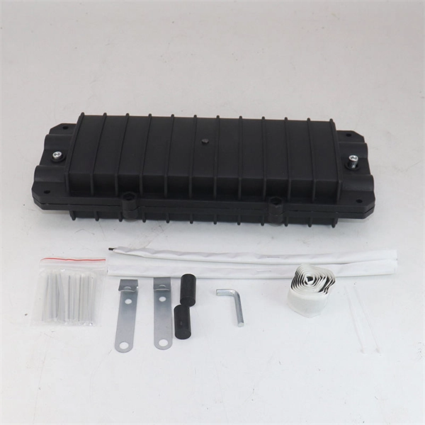
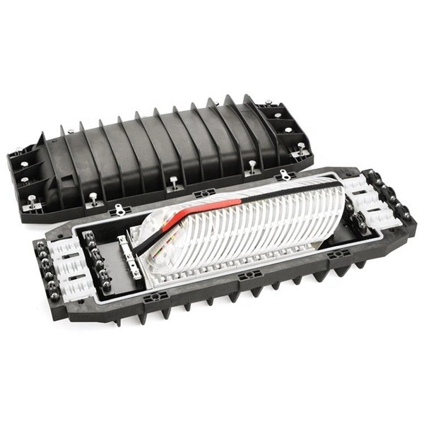
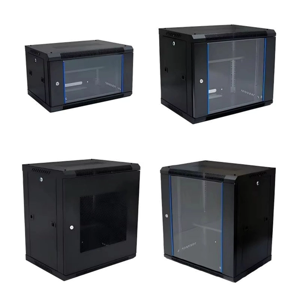
A fiber optic termination box is an enclosure designed to terminate incoming optical fiber cables and distribute optical signals to drop cables or patch cords. It integrates fiber splicing, adapter management, and cable protection in one compact unit. A fiber optic termination box, often called an optical distribution frame (ODF) or fiber patch panel, serves as the endpoint where incoming fibers connect to devices or. A fiber optic termination box is a core component in modern fiber optic networks, providing a secure and organized point for fiber termination, splicing, and distribution. It is widely deployed in FTTH, FTTB, and other access networks to ensure stable signal transmission from backbone cables to end. Fiber termination refers to the process of preparing the end of a fiber optic cable to connect to another fiber, a device, or a network. There are two primary. A Fiber Termination Box, also known as a Fiber Distribution Box, is a crucial component in fiber optic networks. It is a small enclosure that can house and protect the fiber optic cables, splices, and connectors. The fiber termination box. Choosing the right fiber optic terminal box is less about buzzwords and more about matching physics and field reality to your site: where the box will live, how many cores you need now and later, how technicians will access it, and what level of environmental and mechanical protection the network.
[PDF]
When deploying fiber optics in the field, telecommunications companies need ways to safely and efficiently store and terminate cables. As many technicians know, having the right fiber optic patch and splic.
[PDF]
The timeframe for splicing a fiber optic cable can vary depending on the type of splice, the equipment used, and the level of expertise of the technician. In this article, we will delve into the details of the splicing process and explore the. Fiber splicing involves several steps, each requiring attention to detail and precision: The first step is to prepare the fibers for splicing. This involves: The fiber splicing process itself involves: Once the splice is complete, the technician must test the connection to ensure it meets the. Mechanical splices are faster for emergency restoration but have higher typical loss (0. 1dB for fusion) and degrade over time in outdoor environments. A professional splice kit includes: Every splice starts with proper preparation: clean the work area, protect against wind, and. Downloadable one-page analysis available from The Fiber Optic Association also offers cleaving and splicing tips. A chart developed by Fiber Optic Association master instructor Joe Botha helps technicians calculate the amount of time it will take to conduct a fusion-splcing project. The FOA. So in essence, fiber optic splicing is a process used to join two separate fiber optic cables together. There are numerous use cases for fiber optic splicing. Another method of connecting optical fibers is termination or connectorization, which consists of processing the end of a fiber optic bundle so that it can be connected to other fibers or devices through fiber optic.
[PDF]

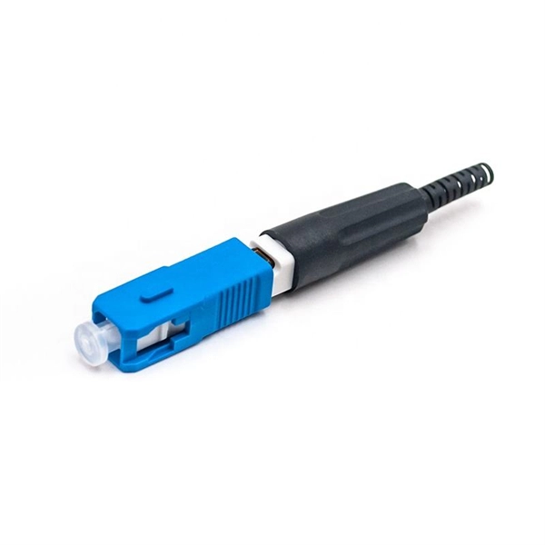
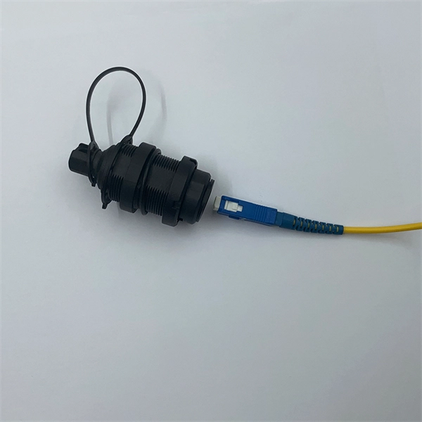
The most efficient way to terminate a fiber run is by using a pigtail. A fiber pigtail is a short length of optical fiber that comes with a high-quality, factory-polished connector already installed on one end, leaving a length of exposed glass on the other. Instead of building a connector from. Installing fiber optic pigtails correctly is essential for ensuring low signal loss and long-term reliability. Remove the outer coating carefully to expose the fiber. Use alcohol wipes to remove dust and debris. Make a precise cut for optimal splicing. Align and fuse the pigtail fiber with the main. Executive Summary: A fiber optic pigtail is one of the most commonly specified yet least understood components in structured cabling. Get the wrong connector type, the wrong polish, or skip proper fusion splicing technique—and you're looking at elevated signal loss, increased back reflection, and a. A fiber optic pigtail is a short length of optical fiber with a connector pre-attached to one end. If you're new to fiber optics or want to enhance your technical skills, this guide will help you understand how to splice fiber pigtails safely and efficiently. --- 🔧 In. Fusion splicing involves precisely melting the ends of two optical fibers together, creating a seamless connection that minimizes signal loss. This method offers the lowest attenuation and reflectance, making it ideal for long-haul telecommunications. You can buy this fusion splicing kit here On.
[PDF]

Learn how to splice fiber optic cable using fusion splicing with this complete step-by-step guide. Includes tools, best practices, loss standards (ITU-T G. 652), cost analysis, and FAQs for network engineers and installers. 5,398 fiber splicing stock photos, vectors, and illustrations are available royalty-free for download. Template technician Fiberoptic Fusion Splicing. Worker connecting for Cable Internet signal and Wire connection with Fiber Optic Fusion Splicing machine,fiber optic cable splice machine in work. Splicing fiber optic cable is an extremely important phase for making dependable, high-speed communication infrastructures. Regardless of the type of fiber network you're deploying, be it for telecom, enterprise data centers, or smart city infrastructure, fusion splicing provides the benefits of. In this guide, we cover the basics of fiber optic splicing, how to perform splicing using two different methods, and finally some best practices to perform good fiber splicing. Ensure Your Splicing Tools are Clean – #2. For network managers and technicians, a poor splice can lead to significant signal degradation, network downtime, and costly troubleshooting. At Turn-Key. 🔧 Watch a real-time fiber optic splicing demo in action! In this step-by-step tutorial, learn how to splice fiber optic cables like a pro — perfect for telecom technicians, network engineers, and field techs.
[PDF]

Access 760 verified Cable Suppliers in Morocco with shipment-level prices, volumes, routes, buyer networks, and verified decision-maker contacts — all backed by bills-of-lading. FBR CABLES designs and manufactures high-performance fibre optic cables in Morocco for operators, integrators and FTTH projects. Backed by advanced production capabilities, we deliver certified quality, controlled lead times and local technical support. The only fibre cable company in Morocco. We are a high quality fiber optic patchcords manufacturer. have several years of experience and very prestigious US European references. based in Morocco, which gives us competitive advantage compare to the other low cost. List of Fiber Optic Companies in Morocco, Suppliers, Distributors. Find and discover Cable manufacturers and suppliers for all products in Morocco, featuring details on their shipment activities, trade volumes, trading partners, and more. View all cable buyers based on products in Morocco. Here are the top-ranked fiber optic cable companies as of May, 2026: 1. Charlton Precision Products, Inc. WIN SOURCE ELECTRONICS, 3. Megladon Manufacturing Group, Ltd. What Is a Fiber Optic. Volza's Global Partner Finder scans 3. Volza's data confirms a robust and dependable Cable supply network. A total. Installation of telecom infrastructure: pylons, antennas. List of suppliers for Cabling- fiber optic networks Morocco. Request for quotes, good deals, exporters.
[PDF]
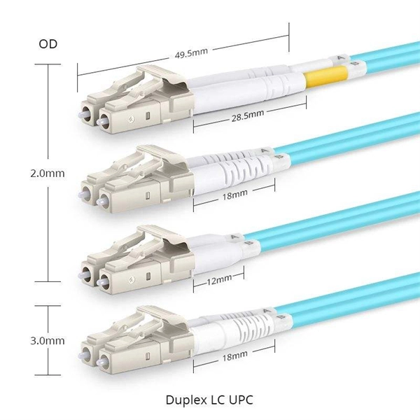
The LC Simplex to Blunt Single-mode (OS2) Splice-On Pigtail provides a dependable solution for terminating 900µm buffered fiber. This 2-meter assembly features a factory-terminated LC connector that is tested for low insertion loss and reliable performance. Leviton fiber optic pigtail kits are a good solution for mechanical or fusion splicing applications. Available in a range of multimode and single-mode fibers with SC, ST or LC connectors. Economy pigtails offer over a. Traditional Fusion Splice-On Connectors with pigtails provide factory-polished performance with field-termination convenience within harsh environments. Mass fusion splicing can fuse up to all 12 fibers in one ribbon at once. Closet Connector Housing (CCH) pigtailed splice cassettes enable faster field splicing and easy modular management of connectorization within the housing. They are preloaded and prerouted for quick fusion splicing of. Get it 12 May, 2026 108 in Global Warehouse. Get it 18 May, 2026 FS offers single mode & multimode fiber pigtails with tight buffer design for easy fusion or mechanical splicing. Quality assurance by 100% end-face, IL & RL testing. Each strand is terminated on one end and the other end is left blunt so that it can be spliced to your drop cable. Our fiber pigtails come with a partial outer jacket to help protect the tight buffer fibers.
[PDF]