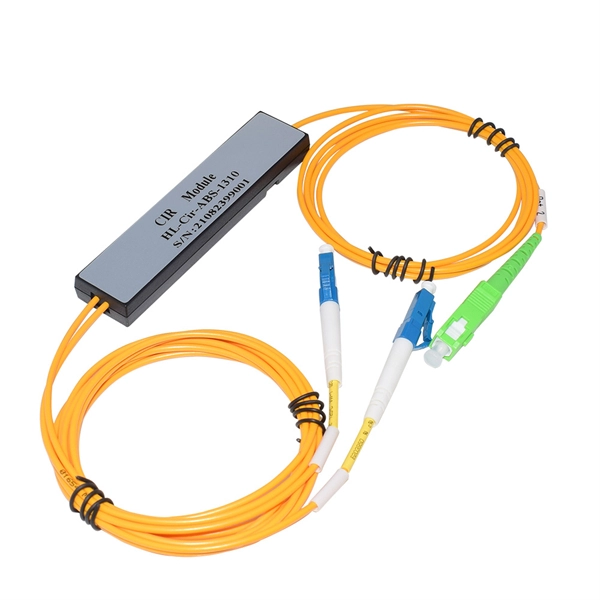
This guide demystifies fiber optic splitters, explaining their design, operating principles, types, key specifications, and real-world applications. Whether you're a network engineer designing a PON (Passive Optical Network) or a homeowner curious about how your fiber connection works. I'm planning to use a TP-Link MC220L transceiver to convert the optical signal to ethernet. This ethernet will then go through a 1 Gbit/s switch, and rout two ethernet cables to each floor. On each floor each ethernet cable will be connected to a router, which will then distribute the internet. DWDM/CWDM is like a two-edged sword. For a small fee (the procurement of the modules and the circulator) you can split/splice one physical fibre optic cable into multiple pairs. The downside is that once you loose your one-and-only fibre link (to a cable-hunting-buck-hoe) then you're in trouble. Fiber optic splitters enable the division of optical signals into multiple paths, allowing information to be distributed to multiple subscribers or devices simultaneously. Understanding the inner workings of fiber optic splitters is crucial for network administrators, technicians, and anyone. The answer is yes, and it's a practice widely used in the industry to distribute signals to multiple destinations without degrading the signal quality significantly. What is Fiber Line.
[PDF]

Connect the fiber optic cable: Attach the fiber optic cable's connector to the transceiver module on the switch. Make sure the connector type (e., SC, LC) matches the transceiver module. In addition, fiber cables can transmit data over several kilometers without signal degradation, making them ideal for connecting switches in large campus networks and between different buildings. As they do not emit electromagnetic signals, they're difficult to tap and secure against eavesdropping. Fiber optic cabling is increasingly used to connect network switches and other datacom equipment, especially in long-distance and mission-critical applications. Fiber provides: Increased internet signal bandwidth. Most modern fiber-enabled network switches require an SFP transceiver module. As we speak I just have optic fibre (Community Fibre) connected to my Huawei modem / Linksys Velop which will be connected to a new POE switch (need to identify the best model to be compatible with my optic fibre extension project). The objective is to run 1 or 2 additional optic fibre from the. Choose an SFP module based on the fiber optic cabling that will be connected to the network switches. SFP transceiver modules almost always require two fiber optic cable strands. Even the most advanced optical transceivers can only perform at their peak when paired with properly installed, clean, and precisely managed fiber.
[PDF]

This section includes all PoE enabled Industrial switches available, including managed models and specific application models like vehicle or substation compliant units. Check each product page for other buying options. Shop products from small business brands sold in Amazon's store. Learn more Need help? Industrial-grade PoE switches for demanding. POE Industrial Ethernet units at Plant Technology USA make Power over Ethernet solutions even more efficient and cost effective. Not only are these de. Read more Find the best Industrial Ethernet Equipment for your project. US-based Customer Support. These rugged, fanless platforms support both Gigabit and 10/100 Mbps Ethernet and offer a selection of fixed-fiber, or SFP uplink. We provide a wide range of PoE/PoE+/PoE++ switches with up to 90 W output per port to deliver high-speed data transmission while powering high-power devices over long distances. With an industrial-grade design, our PoE switches provide surge protection of 4 kV per LAN port. Additionally, Smart PoE. In addition to transmitting network data, a PoE Switch has a built-in Power over Ethernet injector to supply up to 100W Power over Ethernet (PoE) to standards-based 802. 3bt compliant devices such as IP cameras, VoIP phones, and wireless access points. When connecting network.
[PDF]

Optical switches will accept inputs nearly immediately as compared to mechanical switches, which could experience a few milliseconds of debouncing lag. Since optical switches do not depend on physical contact, input latency (latency) is severely minimized. This discrepancy can just be a couple of. An optical transistor, also known as photonic transistor, optical switch or light valve, is a device that switches or amplifies optical signals. Any communication protocol (Ethernet, ATM, etc. Significant. High Speed: Optical switches provide a high-speed data transmission capacity that surpasses that of traditional electrical switches. Interference Resistance: They are immune to electromagnetic interference, ensuring a reliable data transfer. Low Power Consumption: With no need for O-E-O conversion. Optical switching is the process of controlling the destination of individual optical information signals. This technology allows for high bit rate transmission to be switched between various optical lines. The core component enabling optical switching is the Optical Switch. Figure: Optical Switch. Serving as the backbone of high-speed fiber-optic networks, data centers, and emerging technologies like quantum communication, optical switches enable efficient light signal management with a small latency. As global demand for bandwidth surges due to 5G, AI, and cloud computing, advancements in.
[PDF]

Learn how to safely wire a single-pole (one way) light switch in this beginner-friendly tutorial. Whether you're replacing an old switch or doing your first DIY electrical project, this guide will walk you through every step — no experience needed!. more. This page contains wiring diagrams for household light switches and includes: a switch loop, single-pole switches, light dimmer, and a few choices for wiring an outlet/switch combo device. That's because virtually all light switches that control 120-volt fixtures are single-pole switches. Most light switches are also single-throw, which. Summary: Fully explained wiring diagrams and photos show how to wire switches including: single switches, 3-way switches, 4-way switches, and dimmer switches. and Be Sure to Subscribe! Make sure the circuit power has been turned off, and mark the circuit breaker or fuse to indicate that work is. A distribution board or distribution box is where the main power supply is distributed to multiple loads. And all the switching and protective devices are installed in the distribution box. Single Phase Distribution Box generally consists of Double Pole MCBs, Single Pole MCBs, and RCCBs. Wiring a single light switch may seem like a daunting task, but with the right tools, a bit of patience, and this comprehensive guide, you'll be able to tackle this DIY project with confidence. Remember, while this guide provides detailed instructions, always prioritize safety and consult a.
[PDF]
The typical cost of an industrial-grade switch can range from $100 to over $5,000, depending on factors like port count, speed, PoE capabilities, environmental requirements, and advanced network management features. Need help?. Industrial Ethernet switch, also known as industrial switch, is an Ethernet switch used in the field of industrial control. Due to the network standards adopted, it has good openness and wide application. Industrial switch is specifically designed to meet the needs of flexible industrial. When considering the implementation of industrial networks, the cost of industrial switches plays a vital role. A deep understanding of the factors influencing the price is crucial for making informed decisions. In this article, we delve into the various cost considerations associated with. The modular electrical switches manufacturing plant cost report offers insights into the manufacturing process, financials, capital investment, expenses, ROI, and more for informed business decisions. What are Modular Electrical Switches? Modular electrical switches manufacturing is the industrial. IMARC Group's comprehensive DPR report, titled " Electrical Switches Manufacturing Plant Project Report 2026: Industry Trends, Plant Setup, Machinery, Raw Materials, Investment Opportunities, Cost and Revenue," provides a complete roadmap for setting up an electrical switches manufacturing unit.
[PDF]
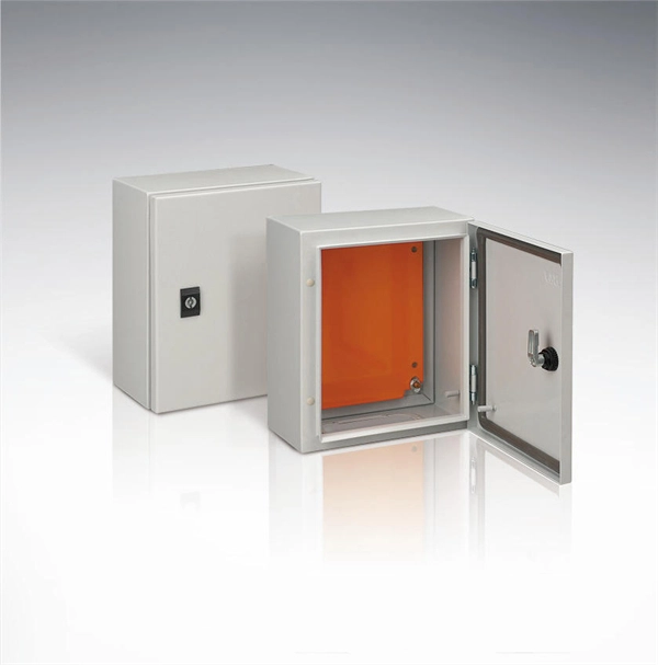
In part two of the 7-part series on how to wire a switch, I explain and demonstrate how to install the cables into a multi-gang box. The video focuses on steps that will both save time and simplify the process. In this video, we'll walk you through the process of wiring a home distribution box with a detailed connection diagram. Whether you're an electrician or a DIY enthusiast, this guide will help you understand the basics of home electrical distribution. Part of my job as a professional electrician is keeping my work neat and organized. A tidy work box makes it easier to install lights, switches, and outlets, and it helps future electricians to see what's going on inside the. Learn how to install a distribution box safely and correctly. Covers wiring, placement, standards, and expert tips for a compliant setup. A distribution box is the heart of any electrical system. It takes the incoming power and safely distributes it to different circuits throughout your building. If you're looking to install a switch box in your home or office, it's important to understand the process involved and the key steps to follow. And all the switching and protective devices are installed in the. According to NEC (National Electric Code: Article 1 00-Definitions), a Main Panel (also known as Panelboard, load center, breaker box and distribution board etc. ) is a cabinet or cutout box which contains on controlling and protective devices (such as circuit breakers, fuses, switches etc.
[PDF]
Insert the end of your fiber optic network line into the fiber optic connector on the converter box. Plug an Ethernet cable into the Ethernet port on the converter box and plug the other end into one of the Ethernet ports on the back of your Ethernet switch. As we speak I just have optic fibre (Community Fibre) connected to my Huawei modem / Linksys Velop which will be connected to a new POE switch (need to identify the best model to be compatible with my optic fibre extension project). The objective is to run 1 or 2 additional optic fibre from the. Connecting a fiber optic switch involves several steps, ensuring compatibility between the switch's ports and the fiber optic cable. Fiber optic switches utilize. Fiber optic cabling is increasingly used to connect network switches and other datacom equipment, especially in long-distance and mission-critical applications. Fiber provides: Increased internet signal bandwidth. Advantages Determine the length of the fiber run and choose either multi mode for runs under 1000 feet or single mode for runs over 1000 feet.
[PDF]

There are 48 bicolor LEDs (green/amber) for the first 48 SFP+ ports and 16 tricolor LEDs (green/amber/white) for the SFP-DD ports. The last set of LEDs pulse once in white before indicating the FC port status in green or amber. When it blinks white twice, it shows the status of the second port of the SFP-DD. The port status LEDs for the FC ports are arranged left and right to correspond to the upper and lower ports respectively in each pair. LEDs on the port side of the switch Table 1. LEDs on Cisco Catalyst 9500 Series Switches 1 Available only on switches with 10G ports. System LED Indicator System is not operational. System is operating normally. As a group or individually, the LEDs show information about the switch and about the ports Preventing Overload - Each port that provides PoE has a maximum power it can deliver. Three LEDs are used on each port. Ports on the Cisco Catalyst switch do not have LEDs. Not the question you're searching for? Each. Number of LEDs per port - Ports that cannot be split; for example, 1G ports must have 1 LED per port. Location - A port LED should be placed right above the.
[PDF]

This guide covers the essential tools and step-by-step procedures for low-loss fiber optic cable repair. Understanding the causes and types of fiber optic cable damage helps detect issues early and determine when repair is needed. Construction Activities: Accidental damage during construction. Step1 : Identify the optical cabinet and network operating center, and find the fiber optic splitter. Step 2: Identify the splitter number. Step 4: Find the optical fiber port and cable sequence that leads to the user. 2) The. This complete guide covers everything from identifying causes of failure to advanced repair techniques, drawing on the latest industry standards and innovations. Whether you're a network technician, IT professional, or telecom operator, you'll find practical steps, tools, and tips to restore. If you accidentally break a fiber optic patch cord in your server room or in any of your switch gear, now you can repair it on the spot and get back up and running in minutes. Adhering to precise methodologies, we can mend impaired cables. By understanding these key elements and following the outlined steps, you can effectively repair fiber optic cables and maintain the high-performance network necessary for today's demanding communication needs. When it comes to ensuring nice network experiences for users, the condition of a fiber.
[PDF]

This quick-reference guide focuses on what to measure, how to interpret results, and what to do when findings indicate marginal performance. Whether you're a network engineer validating new inventory or an integrator preparing for deployment, knowing how to test optical transceiver modules can save time, reduce failures, and ensure SLA compliance. Unchecked optical modules can cause: Testing ensures compliance with IEEE 802. 3 and MSA. This article provides a comprehensive guide on measuring key performance indicators to evaluate the functionality of optical modules, with a specific focus on the sfp28 transceivers. A comprehensive understanding of the working principle of an optical module is essential for determining the. Evaluating the performance of optical modules is a practical discipline: you must verify optical power and signal quality, confirm electrical/optical compliance, validate link-level behavior under real traffic, and document results in a way that supports reliability engineering. This. The optical module serves as a crucial component in optical fiber communication systems, operating at the physical layer, which is the lowest layer in the OSI model. Its primary function is to achieve optoelectronic conversion by converting electrical signals into optical signals and vice versa.
[PDF]
This Cable Sizing Calculator can calculate minimum active, neutral, and earth cable sizes in compliance with the international standard IEC 60364-5-52. It covers all cable types, installation methods, and correction factors in the standards. This guide provides a detailed explanation of cable sizing, including formulas, examples, and tips to help you make accurate decisions for any project. The correct cable size ensures: Safety: Prevents overheating and potential fire hazards. Efficiency: Reduces energy losses due to resistance. Professional electrical wire sizing tool based on National Electrical Code (NEC) standards. Calculate proper wire gauge, voltage drop, and ampacity for safe electrical installations. Input your electrical parameters to get accurate wire size. The calculation follows IEC 60364-5-52 and BS 7671 standards. Selecting the correct conductor cross-sectional area (mm²) is fundamental to electrical safety and system performance. Undersized cables can lead to: Energy inefficiency: Higher I²R losses increasing operational costs. You can estimate. This article examines the sizing of electrical cables (i. cross-sectional area) and its implementation in various international standards. IEC, NEC, BS, etc) and some standards emphasise certain things over others. This cable sizing standard applies to circuits up to.
[PDF]

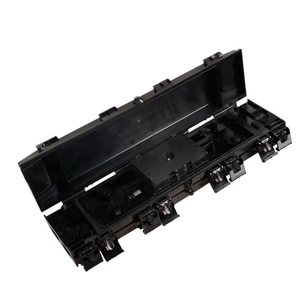
The number of ports in a fiber optic termination box varies from 8 to 96 ports, so you can choose the right junction box for your cable needs. The optical fiber terminal box is the terminal connector of the optical cable, one end is the optical cable, and the other end is the optical cable tail. A Multiport Service Terminal is a hardened, environmentally sealed enclosure that provides multiple pre-connectorized output ports (typically 4, 8, 12, or 16) for drop cables, while accepting a single incoming feeder or distribution cable. Key characteristics: MST boxes are the cornerstone of. The terminal box is a fiber management product used to distribute and protect optical fiber links in FTTH networks. This ethernet port is used to connect the modem to an internet router. Modem router combo devices will generally have four ethernet. A router is more than just a box with blinking lights—it contains multiple ports, each tailored for specific roles, such as LAN, WAN, USB, DSL, and console ports. Understanding the purpose, specifications, and configuration of these ports is essential for achieving maximum network performance. It is also sometimes referred to as an "ONT box" or "fiber box. " What Does an ONT Do? Key Functions Explained Here's a quick breakdown of what an ONT does: The ONT receives light signals from the fiber network and converts them into electrical signals.
[PDF]
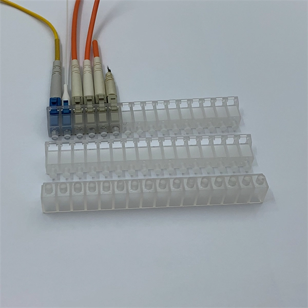
Step1 : Identify the optical cabinet and network operating center, and find the fiber optic splitter. Step 5: Patching from the splitter port to the user. Fiber optic patch cords must be installed correctly to ensure best network performance, reduce signal loss, and protect the sensitive fibers. Whether you're connecting a data center, a corporate network, or a high-density fiber infrastructure, correct installation methods are essential. Yingda. You can put in a fibre patch cord at home. You just need to follow easy steps and be careful. Planning helps you pick the right cord for your network. Be gentle when you handle the cord. Fibre patch cords last longer and are tougher than. This article will guide you through the necessary tools, materials, and methods on how to connect fiber optic cables effectively, ensuring you achieve optimal performance from your fiber optic network. Have a network installation project? Fiber Optic Cables: The primary medium for your connections. NS Comm provides enterprise-grade fiber optic patch cables engineered for maximum reliability and low-loss performance. However, proper installation techniques are essential to unlock their full potential. This guide will help you understand fiber construction, installation steps, real attenuation. Correct patch-cord installation is essential for maintaining low insertion loss, stable return loss, and long-term reliability in both indoor and outdoor fiber networks.
[PDF]

This guide delves into the structure and working principle of fiber optic connectors and outlines the critical steps for creating a successful connection. Proper connection of fiber optic cables is essential to harness these benefits fully, as even minor errors can lead to significant performance issues like signal loss. This article will guide you through the necessary tools, materials, and methods on how to connect fiber optic cables effectively. This guide will explain the entire set of activities involved in installing Fiber optic cable contractors -from the early planning stage right through testing-for facility managers, IT teams, and low-voltage contractors to build high-performance networks safely and efficiently. The processes. However, working with fiber requires specialized skills and equipment to connect cables properly. This guide will walk you through the complete process of connecting fiber optic cable. Before connecting any fiber cable, you need to assemble the proper preparation tools: With the right tools in. The Fiber Optic Association, Inc. (FOA) was founded in 1995 to help develop the workforce to build the fiber optic networks to support a rapid expansion in communications and the Internet.
[PDF]