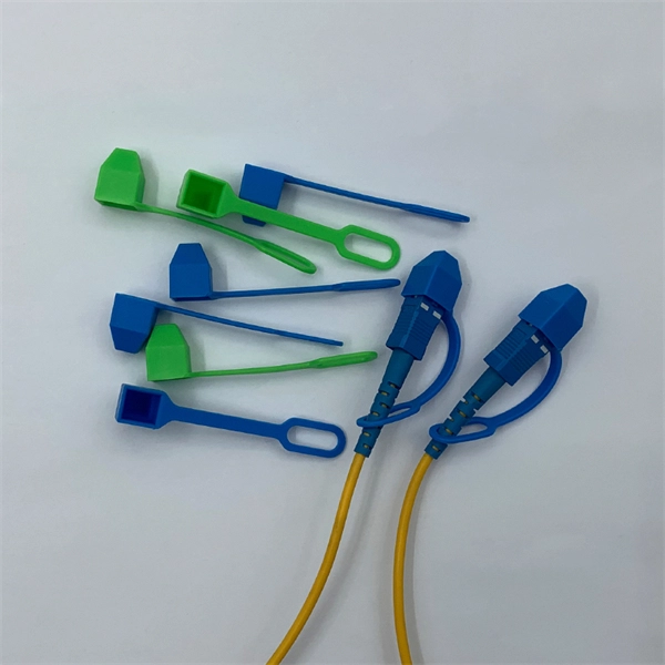
FC-FC patch cords have strictly overdefined precise tolerances between the cable, the optical source, the emitter and the detector that ensures reliable data transfer in high speed fiber networks. The most common choice of application of the FC-FC patch cord is in Video over Fiber Transmission Equipment. You can also use the FC-FC patch cord in many applications such as in data communications, telecommunications, measurement/test equipment, LAN cabinets and single-mode lasers. The FC connector itself is so defined under the IEC 61754-13 stan. With FC-FC fiber optic terminations, your connected device or devices are protected under the harsh and extreme environment situations such as those with high vibrations. OTSCABLE supplies FC-FC fiber optic cable assemblies, with single mode (9/125) and multimode (50/125 and 62.5/125) options. You can choose if it's for riser application or plenum connections or if you want it to be completely customized, you can contact us to know more about our OEM/ODM service for FC-FC patch cords.
[PDF]
Single mode fiber patch cord: Single mode 9/125um optic patch cord are designed for long-distance transmission. They have a smaller core diameter (typically 9 microns) compared to multimodeoptic.
[PDF]

A Mode Conditioning Patch Cord (MCPC) is a specialized fiber patch cord designed to control the launch condition of light from a single-mode transmitter into a multimode fiber. Fiber optic cables primarily come in two types: Multimode Fiber (MMF): Has a larger core, allowing multiple light modes (paths) to travel. It's designed for short-distance, high-bandwidth applications within buildings or campuses. Common types are OM1, OM2, OM3, and OM4. Its primary purpose is to reduce differential mode delay (DMD) and prevent bandwidth limitation when legacy multimode. FS offers OM1 & OM2 mode conditioning fiber optic patch cables (MCP) in any connector & cable length, optimal for eliminating differential mode delay effects. This document describes the installation and use of the mode-conditioning patch cords listed in Table 1. 3z-compliant optical fiber assembly consisting of a single-mode fiber permanently coupled off-center to a 62. 5/125) fiber optic cable by offsetting the Singlemode Laser launch from the.
[PDF]

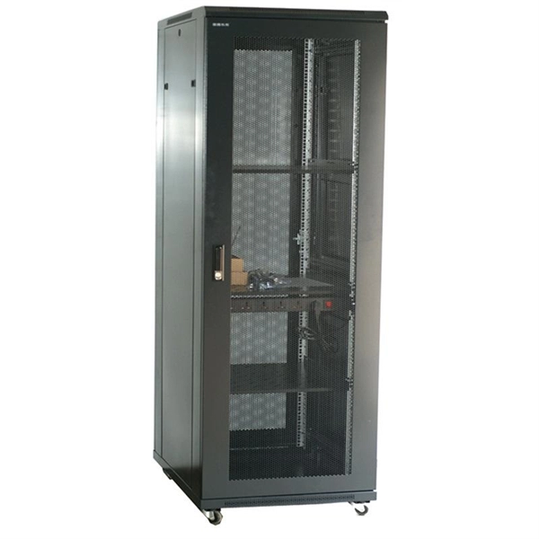
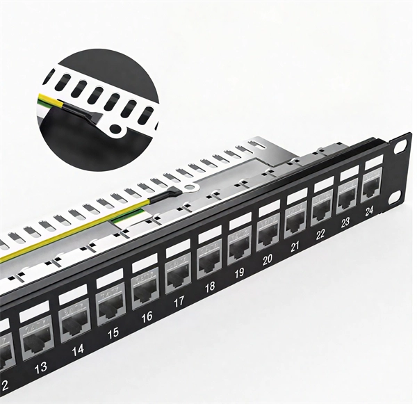
Here's a step-by-step guide to help you properly arrange fiber optic patch panels in a data center environment. Before installation, assess your network's current and future needs:. This guide outlines the key steps and considerations for effective cable management in fiber optic systems. Managing fiber optic patch cables requires strict adherence to technical standards due to the unique material properties of the cables. Even the most advanced optical transceivers can only perform at their peak when paired with properly installed, clean, and precisely managed fiber. Knowing the ins and outs on fiber patch cords and how they are important in server racks Glass fiber patch cords are very slim cables that are excellent at transmitting information quickly and in great quantity. It is essential when racks of servers are used, to maintain a strong and secure. In this configuration, a permanent link is installed between QuickNetTM Patch Panels in the switch/network cabinet and the server or storage cabinets. The most common, flexible, and upgradeable QuickNetTM Fiber Solution is shown in Figure 2, below: In this configuration, permanent links are. Patching fiber optic cable involves carefully splicing two ends together to repair a break or extend a cable run. Here's a breakdown of the process: Assess the Damage and Prepare: Carefully inspect the damage to determine if a patch is feasible. Severely damaged cables may require replacement.
[PDF]

Bend insensitive fiber patch cable is designed to transmit light with minimum loss even if they are bent beyond the bend radius. Fiber optic patch cords are often treated as low-risk consumables, yet a large percentage of optical link failures originate at the patch cord level. Unlike backbone cables, patch cords are frequently connected, disconnected, bent, and handled by technicians, making them the most vulnerable. The bend radius of fiber cables is critical for maintaining high performance and longevity. During installation under tension, maintain a minimum bend radius of 20 times the cable's outer diameter, while post-installation requires a minimum long-term bend radius of 10 times the cable diameter. Fiber optic cables are designed to withstand some bending, but excessive bends can physically damage the glass fiber or cause significant signal loss. That's why every fiber cable has a minimum bend radius specification provided by the manufacturer. The minimum bend radius defines the smallest. When fiber optic cables are bent more sharply than recommended, the internal fibers can break or develop micro-fractures, leading to: Reduced Signal Quality: Noticeable deterioration in signal transmission, including lower speeds and data loss, often results from bending-induced damage. As the bending becomes more acute, more light leaks out (shown in the picture below).
[PDF]
You might have bad connections or lose signal if you bend them too much. Rough handling can also cause problems. Clean them often and manage them with care to stop these issues. If you act early, you will have less downtime. Your network will work better and stay smooth. Proper installation and regular maintenance of fiber optic patch cords play a crucial role in achieving optimized network performance, preventing signal errors, and extending service life. This guide addresses expert-certified best practices applied by professionals in the telecommunications, data. Patching operations must follow principles of neatness, aesthetic cabling, ease of operation, and minimal space usage within ODF frames, optical cross-connects, and integrated boxes. Patch cable lengths should be controlled with a surplus of no more than 500mm. Never use patch cables that are too. Effective fibre optic cable management is crucial for ensuring network reliability, performance, and long-term efficiency. Poorly routed cables, inadequate strain relief, and excessive bending can result in signal loss, increased maintenance, and costly downtime. Incorrect cable lengths can lead to signal attenuation, which refers to the loss of signal strength as it travels through the cable. Plan your fiber patch cord.
[PDF]

Multi-mode fiber optic patch cords utilize a larger core size, typically around 50-100 microns, allowing them to carry multiple modes of light. This design enables the transmission of data over relatively short distances with high bandwidth capabilities. A fiber-optic patch cord is a fiber-optic cable capped at each end with connectors that allow it to be rapidly and conveniently connected to telecommunication equipment. This is known as interconnect-style cabling. A fiber-optic patch cord is constructed from a core with a high refractive. These short fiber optic cords connect transceivers, switches, patch panels, and servers. Without them, even the best optical modules and switches cannot deliver performance. As data rates increase from 10G → 100G → 400G → 800G, patch cables must handle more bandwidth, more density, and stricter. Fiber optic patch cords, also known as fiber optic patch cables or fiber jumpers, are indispensable components in modern optical networks. They act as the critical link for interconnecting devices like optical switches, servers, and distribution frames. Understanding the various technical. Fiber patch cables, also called fiber-optic patch cords, are cables typically containing one or two optical fibers, which are equipped with standardized fiber connectors on both ends. The function of the fiber patch cord.
[PDF]
An undersea fiber-optic cable between mainland Norway and the archipelago of Svalbard in the Arctic Ocean has been lost in a mysterious event. The outage of the submarine telecommunications cable - the northernmost submarine telecommunications cable in the world - follows an accident last year. The. The archipelago still has communication, but no redundancy. Photo: Thomas Nilsen There is no redundant between the Arctic archipelago and mainland Norway after loss of power in the area where the fiberoptic cable follows the seabed down to a depth of 2,700. A diver works on an underwater cable off the coast of Papua New Guinea. Believe it or not, Svalbard, Norway has famously reliable internet — and has since 2003. The remote arctic archipelago sits almost 2,000km away from the mainland, at about 80˚N, but its nearly 3,000 residents have surfed the. LILLESTRØM, Norway — Undersea cables have been transmitting communications since the 1850s, but the now ubiquitous technology is grabbing headlines as NATO nations accuse bad actors of sabotaging fiber-optic lines in the Baltic Sea. Attacks on undersea infrastructure came to the fore in September.
[PDF]

The compact 1 port ftth fiber termination box can hold 2 cores splicing, termination and coil up to 30 meters long for cable management in FTTH network. The 1 port fiber termination box is available for fiber optic cable coiling, it is great to connect optical cable and pigtail and protect fiber splices from damage. It is small, lightweight, and offers the function of fiber splicing, storage, and termination, mainly used in residential buildings. The maximum distance for single mode fiber optic cable can extend up to several hundred kilometers, making it ideal for long distance data transmission. One type of single mode fiber is known as “G. 652,” which is commonly used in telecommunications networks. Here are some general guidelines: 1. The shorter distance accounts for the. A fiber optic distribution box (FDB) is a protective enclosure for managing fiber optic cables. It organizes connections, splices fibers, and distributes signals in networks like FTTH (Fiber-to-the-Home) or FTTB (Fiber-to-the-Building). It acts as a central point for terminating, splicing, and distributing these cables, providing necessary protection and. The Fiber Optic Association, Inc. (FOA) was founded in 1995 to help develop the workforce to build the fiber optic networks to support a rapid expansion in communications and the Internet. The charter of the FOA was to promote professionalism in fiber optics through education, certification, and.
[PDF]
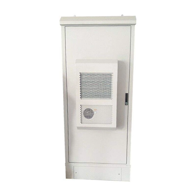
Junction Boxes for fiber optic cable shall be placed along the fiber optic conduit and should be spaced a minimum of every 1500' for Limited Access and non-Limited Access roadways and at all signalized locations or proposed signal locations. Introduction to Fiber Optic Junction Boxes A fiber optic junction box, also known as a fiber optic distribution box or termination box, is a protective enclosure that facilitates the connection and management of fiber optic cables. It serves as a central point for organizing and distributing. Fiber junction boxes play a crucial role in the organization, protection, and distribution of fiber optic cables in various applications, including telecommunications, data centers, and industrial networks. These boxes serve as connection points for fiber optic cables and facilitate efficient cable. A Fiber Terminal Box (FTB) is a customer-side termination and distribution device used at the end of the optical network. These enclosures are essential for protecting fiber connections from environmental hazards and physical damage. As the demand for high-speed internet and reliable telecommunications increases, the. The Fiber Optic Association, Inc. (FOA) was founded in 1995 to help develop the workforce to build the fiber optic networks to support a rapid expansion in communications and the Internet. It houses and protects the connections and terminations of fiber optic cables, providing a central point for managing and organizing the fiber.
[PDF]
The PL-1000D simultaneously monitors up to 16 fiber strands, eight on the OTDR and eight on the OSA, and operates standalone over dark fiber, lighted fiber, or a third party network without impacting network traffic. The device monitors the entire D. The PL-1000D simultaneously monitors up to 16 fiber strands, eight on the OTDR and eight on the OSA, and operates standalone over dark fiber, lighted fiber, or a third party network without impacting network traffic. The device monitors the entire DWDM C-band spectrum and provides the optical spectrum, OSNR, and OTDR measurements of the fiber. The OTDR locates fiber cut by sending high powered optical pulses into the fiber and creating Rayleigh back-reflections. The returning signals are measured and calculated, indicating the accurate location and intensity of the fault. The OTDR supports GIS (Geographic Information System) using Rest API, enabling precise geographic location of disrupt. The OSA enables the user to monitor the OSNR and optical spectrum of each fiber and shows a full, accurate and detailed picture of the wavelengths used in the fiber. OSADiagram Graphical Display of the OSA, from PacketLight's LightWatch NMS Please contact usfor a quote or further assistance.
[PDF]
Typical rates range from $75 to $180 per hour per technician, with on-site time often dominating the total. Hidden costs include traffic control, trench restoration, and post-repair verification testing. When fiber optic cables fail or require maintenance, typical repair costs hinge on incident location, damage severity, and the required equipment. Expect costs to reflect both material needs and labor time, plus any regional price differences. Assumptions: region, cable type, damage extent, and. Buyers typically see repair costs driven by cable type, damage location, and access challenges. The cost to fix a fiber line often hinges on the fault type, distance, and response time, with price ranges reflecting differing crews and materials. Main cost drivers include on-site labor, specialized fusion splicing, testing, and any necessary restoration of network performance. This guide presents cost ranges in USD, with clear. In the United States, fiber optic repair typically costs a few hundred to several thousand dollars, depending on the scope of the fault, distance of the fiber run, and required components. Please see r/Save3rdPartyApps and this article for more information: https://www. com/2023/6/10/23756476/reddit-protest-api-changes-apollo-third-party-apps Cost of fiber line repair? I've had att internet for quite.
[PDF]
In this comprehensive guide, we'll walk through the best practices for installing various types of fiber optic cable, from patch cords to distribution fiber, and provide practical tips to ensure a successful installation. The processes. Fiber optic installation delivers unmatched network performance for modern businesses, providing greater bandwidth capacity and superior resistance to electromagnetic interference compared to traditional copper cables. Professional installation ensures optimal performance and higher reliability for. In the spirit of self-reliance and technical mastery, we've crafted this detailed guide to empower you to take control of your own network by installing fiber optic cables yourself. In this guide, we will walk you through a step-by-step process for the installation of fiber optic cables. The number one cause of signal loss in optical fiber installations is dirt on. In this comprehensive guide, we'll cover everything you need to know about fiber optic cabling—from key components and installation procedures to best practices for network design and maintenance. What is Fiber Optic Cabling? Fiber optic cables transmit data as pulses of light through strands of.
[PDF]
The timeframe for splicing a fiber optic cable can vary depending on the type of splice, the equipment used, and the level of expertise of the technician. In this article, we will delve into the details of the splicing process and explore the. Fiber splicing involves several steps, each requiring attention to detail and precision: The first step is to prepare the fibers for splicing. This involves: The fiber splicing process itself involves: Once the splice is complete, the technician must test the connection to ensure it meets the. Mechanical splices are faster for emergency restoration but have higher typical loss (0. 1dB for fusion) and degrade over time in outdoor environments. A professional splice kit includes: Every splice starts with proper preparation: clean the work area, protect against wind, and. Downloadable one-page analysis available from The Fiber Optic Association also offers cleaving and splicing tips. A chart developed by Fiber Optic Association master instructor Joe Botha helps technicians calculate the amount of time it will take to conduct a fusion-splcing project. The FOA. So in essence, fiber optic splicing is a process used to join two separate fiber optic cables together. There are numerous use cases for fiber optic splicing. Another method of connecting optical fibers is termination or connectorization, which consists of processing the end of a fiber optic bundle so that it can be connected to other fibers or devices through fiber optic.
[PDF]
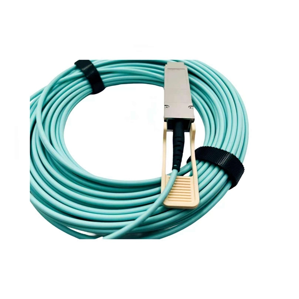
It features a gel-free, water-blocked core and a flame-retardant jacket, allowing safe installation inside buildings and in covered outdoor pathways such as ducts and trays—without the need for splicing between environments. ETK Kablo 's fire-resistant fiber optic cables ensure continuous data transmission during fire conditions, safeguarding critical communication lines when reliability is most crucial. Certified to B2ca CPR and FE180 fire-resistance standards, these cables maintain optical integrity under extreme. In the modern era of telecommunications, flame retardant optic cable play a pivotal role in ensuring seamless connectivity across various devices and networks. These essential components are designed to transmit data efficiently, offering reliability and speed in communication systems. The demand. The flame-retardant Wrapping Tube Cable™ (WTC™) with Spider Web Ribbon™ (SWR™) is a high-density optical cable designed for riser-rated indoor use. Temperature: -20 °C - 70 °C. Optical fibre cable armoured, PKSP sheath 16 to 128 fibres waterproof loose tube singlemode optical fibre cables. MTP|MPO fiber optic patch cable is a powerhouse of performance and durability. The OM3 multimode fiber enables rapid and error-free data transmission, powering.
[PDF]
