Step-by-step instructions on how to install fiber optic connectors like LC, SC, and ST. Includes tool recommendations, epoxy and polish method, and safety tips for installers and technicians. Even with sharing in efficiency, fiber connector installation is still an effort in which precision and safety form the central themes. A correct installation creates a low-loss, reliable connection essential for high-speed data transmission. While fiber optics enable speeds and distances copper can't match, the system's performance hinges. Next, we will introduce in detail the installation of several different types of fiber optic connectors. How To Connect Fiber Optic Cable To Connector? The connection methods for SC, FC, ST, and FT connectors with optical fibers are basically the same. Unlike foil strain gauges, fiber is often suitable for embedment. Sensuron's FOS offers hundreds to thousands of sensing points with a resolution of 1. 4 mm along a single sensing fiber. This video demonstrates the process of installing a fiber optic sensor to a substrate for measuring distributed mechanical strain. Fiber optic connectors are devices that join two fiber optic cables together, allowing the transmission of light signals with minimal loss. They come in various types, such as SC, LC, ST.
[PDF]
Picking up the best router for fiber internet isn't just about going to the market and choosing one of the best wireless routers. Instead, you need to carefully look at its specs, performance, and the type of securit.
[PDF]

Optical fibers or fiber cables can be used for transmitting optical power from a source to some application. In their served areas will be power generating stations, alternative energy sources (solar, wind, geotherman, etc. ), substations for distribution and microgrids. These networks must be monitored and managed to ensure reliable power for the utility's customers. For monitoring and managing networks. Low voltage cables are mounted on poles in the "telecom space," well below power cables. Optical power ground wire (OPGW) is an electrical power ground with fiber optics in the center of the conductor. That conversion can be done with a photovoltaic cell. The Commission, on June 22, 1965, noting that the increasing demand for underground electric and communication facilities in California has brought about substantial increases in the construction of such facilities, and that it appeared it may be desirable, pursuant to Sections 761, 768 and 8056 of. One choice is optical power ground wire (OPGW). This conductive cable is run at the top of the tower or pole to be the ground conductor and protect the power cables from lightning. The fiber. While fiber optics is essential for internet service providers to deliver higher bandwidth and faster transmit speeds, there are also many crucial benefits of fiber optics in energy and power. Utility companies face various challenges as they work to deliver reliable energy to homes and industries.
[PDF]

Fiber optic connector pull test demonstration with real-time insertion loss monitoring. We use an optical loss tester to track signal stability every second while controlled tension is applied to the fiber. more. Fiber optic cable is surprisingly strong, durable and pliable; however, several best practices should be followed to ensure a successful cable installation. The below article explores the best practices and tools commonly used to pull fiber optic cable. The Future Ready Solutions Tools & Test. NEOFIBO TFTM-100N Vertical Fiber Optics Cable Tension Testing Machine The Cable Tensile Testing Machine is a precision mechanical measuring instrument designed to evaluate the tensile strength and elongation properties of various cables, wires, and fiber optic assemblies. Most fiber damage does not come from normal operation after the system is live. It happens during installation, when excessive pulling force, tight bends. Fiber optic connectors are designed to be connected and disconnected many times without affecting the optical performance of the fiber circuit. Optimal performance can be achieved by following the correct process for termination of the fiber circuit—a task which requires the use of a wide range of. The Fluke Networks JR-LEV-1 JackRapid Punch Down Tool is a cable termination tool that is designed to give technicians maximal efficiency in cable maintenance.
[PDF]
Optical fibers carry light signals down them in what are called modes.That sounds technical but it just means different ways of traveling:a mode is simply the path that a light beam follows down the fiber. One mode isto go straight down the m. Optical fibers carry light signals down them in what are called modes.That sounds technical but it just means different ways of traveling:a mode is simply the path that a light beam follows down the fiber. One mode isto go straight down the middle of the fiber. Another is tobounce down the fiber at a shallow angle. Other modes involve bouncingdown. We're used to the idea of information traveling in different ways.When we speak into a landline telephone,a wire cable carries thesounds from our voice into a socket in the wall, where another cabletakes it to the local telephone exchange. Cellphones work a differentway: they send and receive information using invisible radio waves—atechnology call. Light travels down a fiber-optic cable bybouncing repeatedly off the walls. Each tiny photon (particle of light)bounces down the pipe like a bobsleigh going down an ice run. Now youmight expect a beam of light,traveling in a clear glass pipe, simply to leak out of the edges. Butif light hits glass at a really shallow angle (less than 42 degrees), i.
[PDF]
The normal recommendation for fiber optic cable is the minimum bend radius under tension during pulling is 20 times the diameter of the cable (d). This includes pulling tension, minimum bend radius or diameter and crush loads. Installers must understand these specifications and know how to install cables without. Fiber optic cable bend radius is a critical mechanical parameter that determines how sharply a cable can be bent without risking microbending, macrobending, signal loss, or long-term structural fatigue. It is measured from the inside of the bend, not the outer curve. Fiber optic cables transmit data through light propagation within a glass core. The correct bend radius calculation is a fundamental prerequisite for high-quality fiber optic installations and is decisive for long-term network performance and reliability. While installers are aware of the fundamental importance of minimum bend radii, they often lack the practical know-how to. The bend radius of fiber cables is critical for maintaining high performance and longevity. This overview explains key standards, installation best practices, and consequences of exceeding limits during handling, routing, and management. What Is Bend Radius? You need to understand the concept.
[PDF]
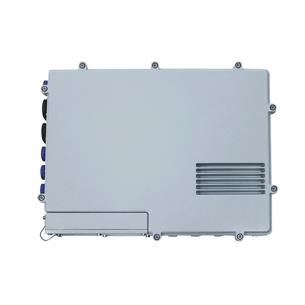
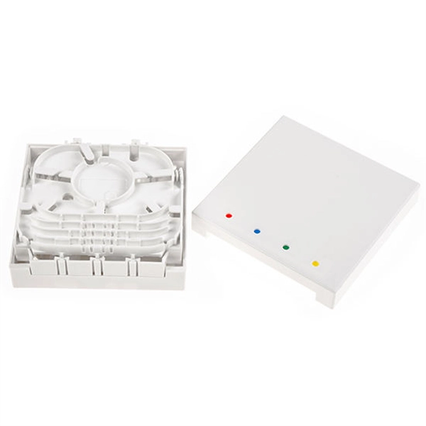
The fiber termination box is an essential component in the realm of fiber optic networks, providing a structured and secure location for splicing, terminating, and managing fiber optic cables. This product not onl.
[PDF]
In this paper, we propose and experimentally demonstrate a Michelson interferometer (MI)-based inclinometer using a simple configuration: a misalignment-spliced single mode fiber (SMF) with end coating. A fiberoptic sensor that uses diverse fiber units to support various applications in virtually any environment. These are reliable and easy-to-use devices that have high power, can automatically adjust to real-time conditions, and have a straightforward display that eliminates any guesswork. This. An in-fiber Michelson interferometer (MI)-based inclinometer, which consists of misalignment-spliced fiber with end coating, is proposed and experimentally demonstrated. The incident light divided at the misalignment-spliced joint is reflected at the end coating, and then re-coupled into the fiber. Jose Miguel Lopez-Higuera: Handbook of Optical Fiber Sensing Technology, John Wiley & Sons, 2002. P 603 Radiation absorption excites an orbital electron to a higher energy level.
[PDF]

They are the bridge between fiber optic cables in the field and the equipment or patch panels that manage them. By combining factory-installed connectors with spliced bare fiber, pigtails ensure that network installers can create fast, reliable, and cost-effective terminations. Fiber pigtails are simple in appearance, yet essential in function. Get the wrong connector type, the wrong polish, or skip proper fusion splicing technique—and you're looking at elevated signal loss, increased back reflection, and a. A fiber pigtail is typically a fiber optic cable with one end factory pre-terminated fiber connector and the other exposed fiber. It is usually suitable for field termination using a mechanical or fusion splicer. Compared with quick termination or epoxy and polish connections placed on the field. ■ What is a fiber optic pigtail cable? A pigtail fiber indicates a short length of optical fiber cable that has a pigtail connector (for example, SC, FC, ST, LC, etc. ) fitted on one end and the other end undressed (for connection through fusion or splicing) to the main fiber optic cable. When compared to field-installed rapid.
[PDF]
Modern fiber-optic communication systems generally include optical transmitters that convert electrical signals into optical signals, to carry the signal, optical amplifiers, and optical receivers to convert the signal back into an electrical signal. The information transmitted is typically generated by computers or.
[PDF]
The backbone consists of approximately 7,910 km of fiber optic cable that connects all regions within Tanzania and provides cross-border connectivity to neighboring countries including Zambia, Malawi, Kenya, Uganda, Rwanda, and Burundi. Tanzania and Kenya have officially inaugurated the redundancy route of the National Optic Fibre Cable network at the Horohoro border post, marking a significant advancement in enhancing digital connectivity and promoting regional integration in East Africa. During the launch event, Tanzania's. Tanzania is contemplating to soon start exporting fibre optic cables since the rate and quality of productivity of modern connectivity backbone continues at the plant located in the country's coastal region. Speaking in Arusha, the Deputy Minister of Information, Communication and Information. The Internet Outages Map is an at-a-glance visualization of global Internet health over the last 24 hours, tracking Internet outages across ISPs, top application providers, public clouds, and edge service networks. Speaking during the launch, Tanzania's Minister for.
[PDF]
Fiber optic transmission distance varies based on fiber type, environmental conditions, and equipment selection. This guide explores the key factors affecting fiber optic transmission distance and provides practical selection guidelines for a stable and cost-effective network. Receiver Sensitivity Higher receiver sensitivity means that it can detect weaker optical signals. Even if the optical signal power is low, the receiver can still detect and decode the signal correctly, extending the transmission distance of fiber optic communication. Another consideration is that. Fiber optic cable transmission distance is determined by two primary physical factors that affect signal quality as light travels through the fiber medium. For most enterprise or data center applications using multimode fiber, the practical limit sits between 300 m and 550 m. Single-mode. Estimate one-way and round-trip timing for fiber runs, optics, and active hops in home labs and backbone links. Direct point-to-point links with OS2 single-mode 1310 nm typically use 10 km+ of practical reach. Configuration type Fiber profile Route length Measured in feet for imperial mode. Apply a waste factor based on site practice. Click Calculate to see totals and the breakdown. Use the export buttons to share results. For critical links, verify on drawings and allow extra for rework. Fiber length takeoff starts with a measured route. Break the pathway into segments for tray runs.
[PDF]

No, fiber optic cables do not conduct electricity. Instead, they transmit light signals. Electricity flows through metal wires as the movement of electrons. On the other hand, optical fibers guide light through glass or plastic strands, and it does not require electrons. Optical fibers or fiber cables can be used for transmitting optical power from a source to some application. That conversion can be done with a photovoltaic cell. While the transmission medium itself – the fiber optic cable – does not require electricity to carry light signals, the infrastructure and devices that make the internet connection functional absolutely do. This is a crucial distinction that often leads to confusion. There are two types of these cables, OPGW (optical power ground wire) and OPPC (Optical power phase conductor) cables. These cables are installed on poles or towers at the. Fiber optic cables are now the main way of carrying information over long distances. They carry pulses of light along flexible glass threads. This is in contrast to copper cables, which carry electrical pulses along their metal strands. While fiber optic cables do not directly carry electricity. Power-over-fiber (PoF) is a technology in which a fiber-optic cable carries optical power, which is used as an energy source rather than, or as well as, carrying data. Light is a form of.
[PDF]
Fiber Drawing, Fiber Assembly, Electronic Assembly and CNC Machining, in house. Fiberoptics Technology Inc. is a leading global supplier of standard and custom designed OEM non-telecom fiber optic components. Corning is opening three new advanced manufacturing plants in the U. The partnership brings together two of the infrastructure companies benefiting the most from the artificial intelligence boom. Corning shares are up more than 250% in the. Corning, once best known for Pyrex and Gorilla Glass, is now at the center of the U. push to build AI data centers. On Wednesday, Nvidia and Corning announced a $500 million deal to build fiber-optic cables to power AI data centers. For Nvidia, which manufactures graphics processing units key to. Corning Incorporated, founded in 1851 and headquartered in Corning, NY, employs over 58,000 professionals and records annual sales exceeding $250 million. As a pioneer in fiber optic technology, Corning sets industry benchmarks through ongoing R&D investment and global market influence. We are headquartered in the United States, where we run three shifts and maintain the. Silicon Valley-based Opticlarity is one of the few actual production companies located in the USA focusing on passive custom optical interconnect solutions such as cables and boxes.
[PDF]
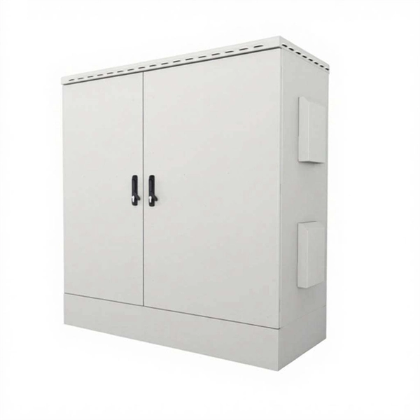
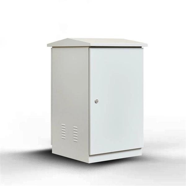
This guide provides a comprehensive engineering perspective on ODFs—beyond the basic “what is an ODF” explanation—covering structural design, fiber management, MPO/MTP integration, and selection criteria for modern high-density deployments. Why ODFs are the Foundation of. This complete guide explores everything you need to know about ODFs — from their structure, types, and key components, to installation best practices and modern design trends. Whether you're building a central office, data center, or FTTx distribution network, understanding the right ODF. In the complex architecture of fiber optic networks, the Optical Distribution Frame (ODF) serves as the linchpin for organizing, protecting, and distributing optical signals. As data centers, enterprises, telecom operators, and smart-building infrastructures deploy increasingly dense fiber links, ODFs provide the structured. An ODF is a central hub in fiber optic networks, crucial for managing and organizing the variety of fiber-optic cables and connections entering a facility such as a telco central office (CO). They provide efficient fiber optic management, connectivity, and protection. What is Optical Distribution Frame An Optical Distribution Frame (ODF) is the central hub of your fiber optic network.
[PDF]