
However, essentially, optical fiber patch cords are more like "finished connection lines", while optical fiber pigtails are "semi-finished connectors". The difference in this core positioning determines the vast disparity between them in structure, connection methods. Executive Summary: A fiber optic pigtail is one of the most commonly specified yet least understood components in structured cabling. Get the wrong connector type, the wrong polish, or skip proper fusion splicing technique—and you're looking at elevated signal loss, increased back reflection, and a. When you build or upgrade a fiber network, the same four words pop up everywhere— fiber optic (bare fiber), pigtail, patch cord, optical cable. They're related, but they are not interchangeable. Mixing them up drives costs higher, increases loss, and slows your rollout. The good news? Once you nail. A fiber pigtail is typically a fiber optic cable with one end factory pre-terminated fiber connector and the other exposed fiber. It is usually suitable for field termination using a mechanical or fusion splicer. The connector end plugs into devices like transceivers or patch panels, while the bare end is typically fusion spliced to a fiber optic cable. This setup ensures. As outlined in T13: Fiber Optic Fundamentals, an optical fiber is a coaxial cylindrical dielectric waveguide with a core refractive index exceeding that of its cladding.
[PDF]
A passive optical network (PON) is a fiber-optic telecommunications network that uses only unpowered devices to carry signals, as opposed to electronic equipment. In practice, PONs are typically used for the last mile between Internet service providers (ISP) and their customers. In this use, a PON has a point-to-multipoint topology in which an ISP uses a single device to serve many end-us. Components and characteristicsA passive optical network consists of an (OLT) at the service provider's central office (hub), passive (non-power-consuming) optical splitters, and a number of (ONUs) or. Passive optical networks were first proposed by in 1987. Two major standard groups, the (IEEE) and the. A PON takes advantage of (WDM), using one wavelength for downstream traffic and another for upstream traffic on a (ITU-T, typically OS2). BPON, EP.
[PDF]
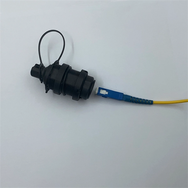
The LEDs have three possible states: no light, a steady light, and a flashing light. Flashing lights may be slow, fast, or flickering. This light shows whether your ONT is getting power. Solid Green: The ONT is powered on and functioning normally. What to check: Make sure the power cable is securely plugged into both the ONT and a working wall outlet. If you're using a power strip, check. The tables in this article provide detailed information about the possible appearances of the LED lights on each device, the possible causes of each state, and what you should do. Ensure your Fiber Jack is connected to the network and the LED lights are connected and working properly before moving. System activity and status can be determined through the activity of the LEDs on the switch. A single tricolor LED for each SFP-DD indicates the port status. When the SFP-DD LED blinks white one time, it shows the status of the first port of the SFP-DD. An ONT may also be called a Service box. If you're having issues and can't get your ONT to power up, contact us. It flashes green during the initialization phase, remains solid green after successful initialization, and turns red when a system fault occurs. When the Status light is red, you can use a PC. Help Centre topics. Fibre ONT devices and how they work.
[PDF]

Configurations of 1x1 to n x m (e., 1x8 or 2x2) are available. The insertion loss of MM switches typically amounts to approximately 0. These switches can be delivered with any of the. Multimode fiber optic switches have emerged as a crucial component, enabling seamless connectivity and efficient data transmission. The MCSW Series Multicast Fiber Optical Switches enable simultaneous connection of one input to all outputs without loss. They support fully non-blocking, conflict-free switching of any number of optical inputs to any outputs, with complete configuration flexibility. The system is entirely passive. The Siemens Scalance X204-2 Multimode Switch requires a 24V UL Listed for Fire Application, Power Limited - Regulated Power Supply. Its Input Voltage is Regulated 24VDC and its Input Current is 265mA @ 24VDC. It is powered from the battery backed up local 24V power supply. Was this helpful? Does. For extremely precise measurement systems and sensor applications as well as for telecommunication applications LASER COMPONENTS offers fiber optical multimode (MM) switches with a fiber core diameter of 50 µm to 600 µm. There are switches are for all different kinds of requirements. Configurations. CONFIGURING THE SWITCH IN DESIGO CC/CERBERUS DMS. CYBERSECURITY DISCLAIMER.
[PDF]
This guide demystifies fiber optic splitters, explaining their design, operating principles, types, key specifications, and real-world applications. Whether you're a network engineer designing a PON (Passive Optical Network) or a homeowner curious about how your fiber connection works. I'm planning to use a TP-Link MC220L transceiver to convert the optical signal to ethernet. This ethernet will then go through a 1 Gbit/s switch, and rout two ethernet cables to each floor. On each floor each ethernet cable will be connected to a router, which will then distribute the internet. DWDM/CWDM is like a two-edged sword. For a small fee (the procurement of the modules and the circulator) you can split/splice one physical fibre optic cable into multiple pairs. The downside is that once you loose your one-and-only fibre link (to a cable-hunting-buck-hoe) then you're in trouble. Fiber optic splitters enable the division of optical signals into multiple paths, allowing information to be distributed to multiple subscribers or devices simultaneously. Understanding the inner workings of fiber optic splitters is crucial for network administrators, technicians, and anyone. The answer is yes, and it's a practice widely used in the industry to distribute signals to multiple destinations without degrading the signal quality significantly. What is Fiber Line.
[PDF]
Insert the end of your fiber optic network line into the fiber optic connector on the converter box. Plug an Ethernet cable into the Ethernet port on the converter box and plug the other end into one of the Ethernet ports on the back of your Ethernet switch. As we speak I just have optic fibre (Community Fibre) connected to my Huawei modem / Linksys Velop which will be connected to a new POE switch (need to identify the best model to be compatible with my optic fibre extension project). The objective is to run 1 or 2 additional optic fibre from the. Connecting a fiber optic switch involves several steps, ensuring compatibility between the switch's ports and the fiber optic cable. Fiber optic switches utilize. Fiber optic cabling is increasingly used to connect network switches and other datacom equipment, especially in long-distance and mission-critical applications. Fiber provides: Increased internet signal bandwidth. Advantages Determine the length of the fiber run and choose either multi mode for runs under 1000 feet or single mode for runs over 1000 feet.
[PDF]

A fiber optic ring network is a physical or logical network topology where devices (usually switches) are connected in a closed-loop using fiber optic cables. Each node is connected to two other nodes, forming a ring-like structure. This design ensures data can travel in both. In this article, we'll explain how to connect multiple Ethernet switches using fiber optic cables and the equipment required for this to work. Network topology refers to the way in which the links and nodes of a network are arranged in relation to each other. If one. Other than entry level network switches, most of today's network switches include one or more GiBC (Gigabit Converter) or SFP (Small Form-factor Pluggable) slots. SFP modules insert into these slots and and require two strands of fiber, typically duplex Using multi mode fiber (for runs under 1000. Fiber optic cabling is increasingly used to connect network switches and other datacom equipment, especially in long-distance and mission-critical applications. Fiber provides: Increased internet signal bandwidth. Most modern fiber-enabled network switches require an SFP transceiver module. Connecting a switch to a fiber optic network involves several steps and requires specific equipment to ensure a successful and efficient connection. Fiber optic technology is widely used in networking due to its high-speed data transmission capabilities and long-distance coverage. This guide will.
[PDF]

This is where a small but mighty hero comes into play: the Mode Conditioning Patch Cable (MCP). In this guide, we'll demystify what a mode conditioning patch cable is, why it's essential in specific network scenarios, and how it can save you from a world of connectivity headaches. This guide offers the key technical insights you need to select and install the optimal fiber optic cabling solutions for your specific needs. Covers the basics of fiber optic technology, including how light waves transmit data through thin strands of glass or plastic, and why fiber optics surpass. Fiber optic cables use light to transmit data, whereas traditional cables rely on electrical signals, which are more prone to interference and loss over distance. Connector types play a crucial. Fiber optic technology has transformed the way we transmit data, enabling faster, more reliable connections than traditional copper cables. Understanding fiber optic cable types is essential for anyone looking to build or maintain efficient fiber networks. We'll also. This is a plain-English guide for facilities and IT teams who want fiber that performs well, stays organized, and doesn't turn every add/change into a disruption. Start with the link's distance and speed, then pick single-mode (OS) or multimode (OM)—not the other way around.
[PDF]

This helps keep fiber optic cables safe from harm and signal problems when you put them in. Use the right lubricant. Follow the rules for tension and bend radius. Try new methods like air blowing. Use smart. Fiber optic cable is surprisingly strong, durable and pliable; however, several best practices should be followed to ensure a successful cable installation. This article explores recommendations for pulling and installing fiber optic cable. This makes sure the cable pull is smooth and safe. Use smart monitoring devices. The Future Ready Solutions Tools & Test. A duct is available from point A to point B, a pull tape is blown in, a fiber optic cable is attached to it and the cable is pulled through the duct. Sounds simple, doesn't it. Recent observations and conversations with more than a few people in the fiber optic business have indicated. Route plan to ensure the duct run maintains the minimum bend diameter of the cable. For more information and all recommendations for installation, refer to Corning Optical Communications Standard Recommended Procedure SRP 005-011, "Duct Installation of Fiber Optic Cable". more Route plan to ensure.
[PDF]

This is the most fundamental ring topology, formed by connecting three or more switches in a closed loop using fiber optic cables. Data can flow in either direction, allowing the network to recover quickly if a link fails. If you have multiple Ethernet switches that need to be connected over long distances, fiber is obviously a preferred choice. Moreover, when it comes to bandwidth, no currently available technology is better than single-mode fiber. It can provide significantly higher bandwidth and carry more data. A single 6 strand fiber can only connect 3 switches back to the core. How many switches do you plan to connect? A star is great for a limited number of switches. I have maybe 20 coming back to my cores. Rings are generally not done anymore, but I think that is for bandwidth as much as anything else. The mainline of the fiber optic LAN directly connects to the switch, then to the router. The connection between two or more Ethernet switches in a certain way (Uplink port, etc. ) is called the cascade. All switches have two fiber ports. Is the best way to have fiber backbone switch and connect fiber channel from every switch to the backbone? Or connect switch 1 to switch 2 to switch 3 to. switch 12 to switch 1 again? Thanks! Let's get some. I need to connect 4 Floor Building with 4 Cisco 2960 - 48 ports switch each other and it needs to be through a fiber. This design ensures data can travel in both directions.
[PDF]
In this informative video, learn how to seamlessly integrate fiber optic cables with Power over Ethernet (PoE) systems for enhanced connectivity and performance. This installation guide focuses on what a patch panel does, patch panel installation basics, and how to connect patch panel to switch while keeping cabling clean and easy to manage. Switch: What's the Difference? Although a patch panel and a switch can look similar in a rack, they. Fiber patch panels are important components that are used to help organize and protect fiber optic cables. Connecting a fiber patch panel to a switch is a critical step in setting up a fiber optic network. Identify. If the PoE switch has SFP slot built-in, what you need is the SFP module installed in the slot. Firstly, Insert the SFP module into PoE switch's SFP slot. Discover the advantages of using fiber optic cables in conjunction with PoE and gain insights into the necessary components required for. If you have an existing patch panel the short answer to “can I just plug in a cable into the front of it” is yes. In comparison to wiring up individual networks, patch panels are much more efficient and can provide more reliable, faster connections. This article will.
[PDF]

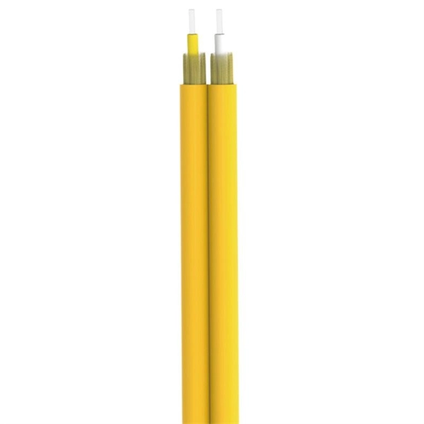
A single strand of glass fiber, called single-mode fiber, is used to transmit single-mode or light beams. It can transmit higher bandwidth than multimode fiber but requires a light source with a limited spectral range. There are mainly two types of optical fibers, single-mode optical fiber, and multimode optical fiber, which differ in the way light propagates. The latter is used for short-distance transmission, while the former is typically used for long-distance signal transmission. Please refer to the article. Single fiber modules (BiDi) use one fiber for both transmitting and receiving data. This saves space and money. Dual fiber modules use two fibers. They are easier to set up and give steady communication. Single-mode optical modules are best for long distances and fast speeds. Modes are the possible solutions of the Helmholtz equation for waves, which is obtained by combining. Optical fiber transmission is based on the principle of total internal reflection, where light signals are transmitted through a thin glass or plastic fiber with a core and cladding. The core has a higher refractive index than the cladding, causing the light signal to be reflected back into the. OS1 single mode fiber optic cables are made with a single mode fiber core, which means that they have a very small core diameter of 9 microns. Each type serves distinct applications based on its light transmission characteristics. Very small core (~8–10 µm). Carries one light path (mode).
[PDF]
The proposed study will be based on three components, namely: (A) support to the establishment and operationalisation of the Digital Development Agency (DNA); (B) the elaboration of a Master Plan for the development of broadband infrastructures, a decision support tool for the. The proposed study will be based on three components, namely: (A) support to the establishment and operationalisation of the Digital Development Agency (DNA); (B) the elaboration of a Master Plan for the development of broadband infrastructures, a decision support tool for the. This intervention concerns the support to the setting up and operationalisation of the National Digital Agency (ADN), the elaboration of a Master Plan for the development of broadband infrastructures and the complete feasibility studies of the Central African Fiber Optic Corridor, DRC component. OTTs and telcos, such as Facebook or Orange, supported by funders and African governments, have joined forces to accelerate the deployment of high-speed connectivity infrastructures. The Congolese Minister of Telecoms, Augustin Maliba, signed the related memorandum of understanding (MoU) on April 7, 2025. "With the support of the. Learn about the market conditions, opportunities, regulations, and business conditions in congo, the democratic republic of the, prepared by at U. Embassies worldwide by Commerce Department, State Department and other U. agencies' professionals Democratic Republic of the Congo -.
[PDF]

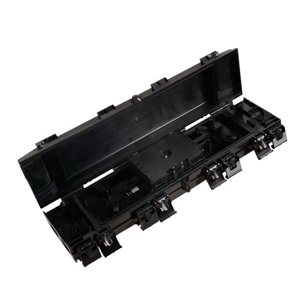
An armored optical cable is a type of fiber optic cable reinforced with a protective layer—usually corrugated steel tape (STA) or steel wires (SWA) —to shield the internal fibers from external threats such as crushing, rodent bites, moisture, and harsh installation conditions. With a durable protective layer, they are ideal for harsh or high-traffic environments. This article explains what armored fiber cables are, their key. Every optical fiber cable project faces the same critical question: should you choose an armored cable or a non-armored one? At first glance, the choice may look simple. Armored cables appear stronger, non-armored cables are cheaper. But the real decision is not that easy. The wrong choice can: Or. With the increasing demands on high-performance connectivity, for many buyers, choices boil down to two quite popular options: the outdoor armored fiber optic cable and the standard optical fiber cable. In this blog post, we'll explore the advantages and disadvantages of. Armored and non-armored fiber optic cables are engineered for different levels of mechanical protection, environmental resistance, and installation conditions. You select between them based on route exposure, rodent risks, burial requirements, tension loads, and overall ODN architecture. An under-armored cable in a harsh environment leads to fiber damage, network outages, and costly repairs. Over-specifying armored cable where standard cable suffices.
[PDF]
The SFP port is commonly found on Gigabit Ethernet switches and is primarily used for fiber optic device connections or for uplinking 1G switches to aggregation/core layer devices, providing higher-bandwidth links. You can add a compatible SFP transceiver module to the SFP port of. SFP ports enable Gigabit switches to connect to a variety of fiber and Ethernet cables and extend switching functionality throughout the network. Small form-factor pluggable is a hot-swappable interface used to connect network and storage switches and transfer data. Switches with SFP ports can. Choose an SFP module based on the fiber optic cabling that will be connected to the network switches. SFP transceiver modules almost always require two fiber optic cable strands. In this guide, we'll cover the following: What is an SFP port? Why is the SFP port important? SFP vs. QSFP28. Enterprise LANs use the RJ45 port on 100/1000BASE switches. It connects access layer devices and uplinks from desktop switches or directly to end devices. RJ45 ports remain essential for. An SFP switch uses Small Form-Factor Pluggable (SFP) modules to form a network switch for high-speed connectivity between devices. These interchangeable modules support various media types, including copper or fiber-optic cables, providing flexible networking options based on specific requirements.
[PDF]
