Download the list of Fiber Optic Products Suppliers in Western Asia as of May 05, 2025 with and without website information. 25% increase from 2023. 10% of all Fiber Optic Products Suppliers in Western Asia are single-owner operations, while the remaining 7 which. Here are the top-ranked fiber optic connector companies as of May, 2026: 1. Thermalogic Corporation, 2. These. Fiber Optic Connectors are an essential component of any fiber optic network that provides a secure and reliable connection between two fiber optic cables. The leading manufacturers of Fiber optic connectors are listed below. Narrow down on the list of companies based on their location and. AFL, based in Duncan, South Carolina, is a prominent manufacturer of fiber optic products and solutions. Established in 1984, the company has built a reputation for delivering high-quality products that cater to the telecommunications and industrial sectors. AFL's extensive product line includes. UnitekFiber produces high quality of MPO|MTP Cables, Fiber Optic Patchcords, SFP Optical Transceivers, MPO|MTP Patch Panels and Outdoor Fiber Cables. We design, create and deliver reliable and cost effective fiber optic products to meet customers' business goals. Our international database.
[PDF]

Fiber optic connector pull test demonstration with real-time insertion loss monitoring. We use an optical loss tester to track signal stability every second while controlled tension is applied to the fiber. more. Fiber optic cable is surprisingly strong, durable and pliable; however, several best practices should be followed to ensure a successful cable installation. The below article explores the best practices and tools commonly used to pull fiber optic cable. The Future Ready Solutions Tools & Test. NEOFIBO TFTM-100N Vertical Fiber Optics Cable Tension Testing Machine The Cable Tensile Testing Machine is a precision mechanical measuring instrument designed to evaluate the tensile strength and elongation properties of various cables, wires, and fiber optic assemblies. Most fiber damage does not come from normal operation after the system is live. It happens during installation, when excessive pulling force, tight bends. Fiber optic connectors are designed to be connected and disconnected many times without affecting the optical performance of the fiber circuit. Optimal performance can be achieved by following the correct process for termination of the fiber circuit—a task which requires the use of a wide range of. The Fluke Networks JR-LEV-1 JackRapid Punch Down Tool is a cable termination tool that is designed to give technicians maximal efficiency in cable maintenance.
[PDF]
However, extreme cold, ice, or snow can affect the cable's outer jacket, cause physical stress, or damage connectors if not properly installed and protected. Using high-quality, outdoor-rated fiber and proper insulation ensures durability and reliability. Optical fiber is also harder to hack than copper, making it more secure and safer because it doesn't generate heat. There is, however, a challenge to be overcome: the delicate nature of the optical fiber means installation and maintenance must be carefully managed. Tiny amounts of grease, dirt or. Summary : Winter weather generally has minimal impact on fiber optic cables since they transmit data through light rather than electricity, making them resistant to temperature-related signal loss. What Is Fiber-Optic Internet? Fiber-optic internet works by transmitting data as pulses of light through ultra-thin. Fiber optic cold connection, also known as mechanical splicing, is a widely used method of connecting optical fibers in a network. Unlike fusion splicing, which uses heat to join two optical fibers together, cold connection uses mechanical means to create a stable and low-loss connection.
[PDF]

Even when a network is designed correctly, real-world conditions—fiber handling, connector cleanliness, splices, environmental stress, and aging—can gradually increase attenuation or introduce reflections and interference. Fiber optic patch cords are often treated as low-risk consumables, yet a large percentage of optical link failures originate at the patch cord level. Unlike backbone cables, patch cords are frequently connected, disconnected, bent, and handled by technicians, making them the most vulnerable. Optical attenuation is the gradual loss of flux (light intensity) as an optical signal travels through a fiber. Measured in decibels (dB), it's the logarithmic ratio of the output power to the input power. Every network has a "loss budget". Field guide for diagnosing high fiber optic attenuation. Learn to use the OTDR to identify contamination, micro-bends, and poor splices, ensuring your 400G network links remain within budget. This article explains practical, engineering-focused ways to mitigate signal. This measurement helps determine the efficiency of a fiber optic system. Several factors contribute to signal attenuation. These include absorption, scattering, and bending losses. Each factor plays a significant role in the overall performance of a network. Whether you're a network engineer, IT manager, or service provider, understanding these challenges and how to address them is critical for maintaining high-performance, reliable.
[PDF]

Optical return loss is the amount of light that is reflected back to the source, this reflected light is measured at each connector and splice at each point over the entire fiber link. This is always measured in dB (decibels) and will be displayed as a negative number. The closer the number is to. The polish of a singlemode fiber endface plays a significant role in reflectance. Understand what you need before you specify. The Institute of Electrical and Building the ORL story Electronics Engineers (IEEE) recently Within a fiber-optic channel or path-released new specifications within way. Optical Return Loss (ORL) in fiber optics refers to the amount of light that is reflected back toward the source in a fiber link. ORL is usually expressed in decibels (dB) as a positive value, with. Return loss (RL) is also called reflection loss. When high-speed signals enter or exit a part of an optical fiber, such as an optical fiber connector, discontinuity and impedance mismatch may cause reflection, which is the return loss of an optical fiber. Poor ORL is commonly caused by dirty connectors, poor splices, mismatched connector types, or damaged fibers. ORL is measured using ORL meters. Home Coherent Optics Optical Return Loss (ORL) Explained Comprehensive Guide to Understanding and Managing Back-Reflections in Fiber Optic Systems What is Optical Return Loss (ORL)? Optical Return Loss (ORL) is a critical parameter in fiber optic systems that quantifies the amount of light.
[PDF]

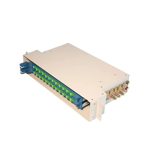
The primary function of a fiber adapter panel is to provide a housing for fiber optic adapters or connectors. These adapters act as the interface between the terminated fiber ends and the active equipment, such as switches, routers, or servers. A fiber patch panel is a mounted enclosure—either rack-mounted or wall-mounted—used to terminate, manage, and interconnect multiple fiber optic cables. It acts as a hub for organizing splices and patch cords, streamlining fiber management and preserving signal integrity. This guide will focus on elucidating the aspects of the fiber patch panel, its accessories, the work done with such a device, and how to. Fiber optic networks are the backbone of fast, reliable internet and modern communications, but even the best fiber cables need the right connectors and patch panels to work efficiently. Connectors are the points where fiber cables link to devices, equipment, or other cables, and using the right. The fiber optic patch panel, also known as the fiber distribution panel, serves as the crucial component of the management of fiber optic cables. Also, the advantage of fiber optic patch panels is to reduce the loss of fiber optic transmission and facilitate engineers to troubleshoot. Serving as the network's centralized junction, it provides secure ports for both incoming and outgoing fibers, streamlining connection.
[PDF]

Fiber optic loss calculation formula: Total link loss (LL) = Cable attenuation + Connector attenuation + Fusion attenuation [Note: If there are other components (such as attenuators), their attenuation values can be added]. Intrinsic Optical Fiber Losses comprise of absorption loss, dispersion loss and scattering loss caused by the structural defects. The detailed information about these optical losses and how to reduce them are. Calculate fiber optic signal loss based on cable length, attenuation, and connector losses. Determine cable loss, connector loss, and total system loss in decibels (dB) to assess signal quality and repeater requirements. Fiber optic loss is calculated in two parts: cable loss and connector loss. This calculator determines fiber loss based on input power, output power, and the length of the fiber optic cable. In summary, fiber optic loss is. Use this worksheet to input values for all variables that will impact your system's performance. After entering your values, please ensure you click the 'Calculate Link Loss' button at the bottom of the page to generate your total link loss. This step is necessary to see if your system falls within. Optical fiber loss is a term for signal loss affecting transmission reliability. Optical fiber loss is.
[PDF]
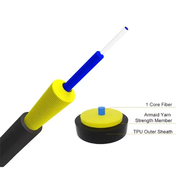
GYTS is a model designator for outdoor fiber optic cable. 'G' indicates it's for outdoor use, 'Y' for its Polyethylene (PE) sheath, 'T' for the gel-filled loose Tube structure, and 'S' for the corrugated Steel tape ar.
[PDF]
One of the most frequent problems in fiber optic networks is signal loss —the gradual reduction of optical power as light travels through the cable. Causes include excessive bending, dirty connectors, or poor splicing. Check for sharp bends or kinks along the cable route. Fiber-optic cables are the backbone of modern connectivity—powering 5G networks, global internet backbones, and data center interconnections with near-light-speed data transmission. While these cables are engineered for durability (with some rated to last 25+ years), they are not invulnerable. Even. When fiber optic cable is stretched or compressed, it can cause physical damage. This is a situation where a cable maintenance is required. This can cause either microbends or macrobends. However, in real-world installations, whether underground, aerial, or in harsh industrial environments, fiber cables can and do fail. Understanding the common causes of. Fiber break, broken fiber is divided into two types: partial interruption and the entire optical cable interruption Partial interrupts are of the following categories: The first reason is that the fiber core is interrupted due to external force extrusion or excessive bending. This guide lists the actual, field-proven problems technicians encounter most often and gives step-by-step troubleshooting actions you can copy into your maintenance routine. Keep. Understanding the common causes and solutions helps maintain stable and efficient connections.
[PDF]
There are several diagnostic methods to help troubleshoot fiber optic connectors, and the diagnostic method is to cross-section the fiber optic connector. This technology allows us to actually look inside the fiber optic connector to see defects and pinpoint the cause of. Fiber design and transmission technology have collaboratively evolved to increase bandwidth. Dig-ups dominate! Cablers have very little influence on the majority of causes of cable field failures. While a small percentage, we can examine the “intrinsic” cable failures and what is done to prevent. Connector failure is most frequently the result of a dirty or damaged end-face. Fiber-optic connector: SC type In the connector, the element that holds the fiber and provides the alignment positioning is the ferrule. The. In August of 1999, Boeing Corporation (Boeing) engineers being used on International Space Station flight a defect in the glass fiber (see Figure 1, “Rocket and NASA engineers and managers, Boeing created and reliability of the cable installed in the U. Fiber coupling can be accomplished by fusion splicing.
[PDF]

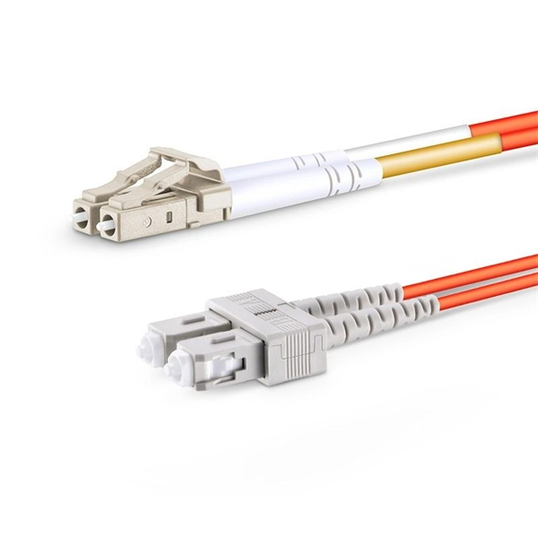
Step-by-step instructions on how to install fiber optic connectors like LC, SC, and ST. Includes tool recommendations, epoxy and polish method, and safety tips for installers and technicians. Even with sharing in efficiency, fiber connector installation is still an effort in which precision and safety form the central themes. A correct installation creates a low-loss, reliable connection essential for high-speed data transmission. While fiber optics enable speeds and distances copper can't match, the system's performance hinges. Next, we will introduce in detail the installation of several different types of fiber optic connectors. How To Connect Fiber Optic Cable To Connector? The connection methods for SC, FC, ST, and FT connectors with optical fibers are basically the same. Unlike foil strain gauges, fiber is often suitable for embedment. Sensuron's FOS offers hundreds to thousands of sensing points with a resolution of 1. 4 mm along a single sensing fiber. This video demonstrates the process of installing a fiber optic sensor to a substrate for measuring distributed mechanical strain. Fiber optic connectors are devices that join two fiber optic cables together, allowing the transmission of light signals with minimal loss. They come in various types, such as SC, LC, ST.
[PDF]
This guide will walk you through the most common fiber connector types, explaining their characteristics, advantages, and typical use cases. Created by the Fiber Optic Association as an educational project to help document the history of the development of fiber optics for communications. Since I was involved in fiber optics starting in the late 1970s, much of this is from personal experiences and memories. Whether you're planning an FTTH deployment, upgrading a data center, or working in telecom infrastructure, this guide will help you make informed decisions. This is the FOA's Online Guide To Fiber Optics, Fiber Broadband & Premises Cabling. It includes almost a thousand pages of materials created by the FOA covering the basics to advanced topics on fiber optics and premises cabling. The goal of this website is educating students, users, designers. Fiber connectors, also called fiber optic cable connectors, are often used to link optical fibers where a connect or disconnect capability is needed. Fiber optic cable connectors come in many configurations and usages, and simplify fiber optic cable installation and maintenance greatly. A number of. This tutorial will provide a brief analysis of the current fiber optic connectors market and a detailed introduction to Fiber optic connectors. Fiber optic cables are increasingly replacing.
[PDF]
The Asia-Pacific fiber optic connector in telecom market is analyzed and market size insights and trends are provided by country, product type and cable type as referenced above. The countries covered in the.
[PDF]

Fiber optic connectors can be categorized according to different standards such as utilization, fiber count, fiber mode, and transmission method. They are also divided into single-mode and multimode types based on their distinct characteristics. This guide will walk you through the most common fiber connector types, explaining their characteristics, advantages, and typical use cases. Whether you're planning an FTTH deployment, upgrading a data center, or working in telecom infrastructure, this guide will help you make informed decisions. Compared to Copper cables, Fiber connector types are incredibly varied. Where copper twisted pairs tend to terminate with an RJ45 plug, fiber optic connectors come in all sorts of shapes and sizes, with all manner of different use cases in mind. An optical fiber connector is used to join optical. With a wide variety of connector types available, choosing the right connector for your network can be challenging. Learn how each connector works, where it's used, and how to choose the right option for today's high-density, high-speed networks. It is a precise coupling device that joins fiber optic cables quickly, enabling faster connection and disconnection than splicing. The connector mechanically orients the fiber cores, allowing light to pass and travel through. In this guide, you'll explore various types of fiber optic cable connectors, each with unique features and best uses. We'll also provide practical advice.
[PDF]
In 2011, the Malian government announced a 942 km fibre optic cable project linking Bamako-Gao-Kidal-Tin-Zaoutière to the Algerian border and Gap-Ansongo-Labezanga to the border of Niger. The project was funded by a $45 million loan from the Exim Bank of China.OverviewThis is a list of projects in. While are used to connect. This list was initially developed as part of AfTerFibre, a project to map terrestrial fibre optic cable projects in Africa. The project was sponsored by and, on completion, will be hosted by the UbuntuNet. • • • •.
[PDF]