
This section explains that Article 250 focuses on general grounding and bonding electrical installation requirements, including: The grounding of systems, circuits, and equipment. Which circuit conductor must be grounded. Learn about the general requirements for grounding and bonding in line with the NEC 2023. The purpose of grounding is the safety of people and property. Grounding and bonding limit overvoltages, stabilize the voltage to the ground during regular functioning, and ease the proper operation of circuit. Electrical grounding is the process of connecting the non-current carrying parts of your home's electrical system—like metal boxes and appliance chassis—to the earth. In the event of a fault, such as a live wire touching a. Correct grounding of services depends upon understanding the definition and role of the grounded conductor. The neutral conductor is typically the grounded conductor connected to the system's neutral point, carrying current under normal operation. Grounding electrode conductors must be connected at. Properly grounding an electrical panel is one of the most critical safety measures in any home's electrical system. It is a non-negotiable requirement for protecting against severe electrical shocks, preventing electrical fires, and safeguarding sensitive electronics from power surges. The main goal of grounding is to limit voltages caused by lightning, line surges, or accidental contact with.
[PDF]

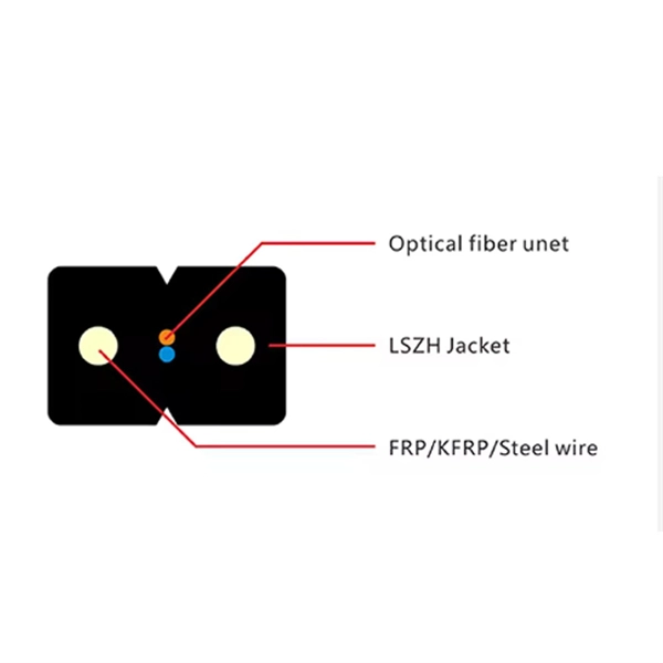
It includes first determining the type of communication system (s) which will be carried over the network, the geographic layout (premises, campus, outside plant (OSP, etc. ), the transmission equipment required and the fiber network over which it will operate. Fiber optic network design refers to the specialized processes leading to a successful installation and operation of a fiber optic network. It also involves selecting transmission equipment. It includes detailed mapping of backbone, distribution, and drop connections for FTTH, FTTP, FTTx, and enterprise networks. Building a fiber optic network is a highly technical yet vital process that enables communities and businesses to access high-speed, reliable fiber optic internet. From the initial site survey to the final fiber to the home (FTTH) connection, every stage requires careful planning, coordination, and. Designing a fiber optic network is like planning a city's road system, it needs to be efficient, reliable, and built to handle both current and future traffic. Whether you're new.
[PDF]

For renewable energy applications, specifically in wind and solar power plants, the IEEE C37. 232 standard specifies the requirements for relay protection of these systems. For those not familiar with the different elements that form a WEP, commonly known as a Wind Farm, this report introduces a description of the different elements comprising a wind farm and how their unique characteristics may be considered to provide a proper design. For successful application of. Abstract—A wind electric plant (WEP) is made of many wind turbine generators spread over a large area and includes many subsystems that need to be protected. It is important to ensure that all the subsystems are well protected and coordinated to maximize the reliability (security and dependability). Protection of Wind Electric Plants is a report covering engineering considerations for the design of protection systems and present relay protection and coordination practices at wind electric plants. The report includes protection of generator step up transformers, collector system feeders. In this paper, the performance of classical protection functions of two commercial relays (denoted as A and B) are investigated. The relays are tested in a Hardware-In-the-Loop environment and the strengths and weaknesses of these functions are determined. These specialized switches serve as crucial safety mechanisms that isolate circuits.
[PDF]

Selecting the right distribution board types depends on load capacity, circuit protection requirements, and compliance with IEC 61439 and SASO standards mandatory in Saudi Arabia. Engineers evaluate voltage rating (230V/400V), form of separation, and environmental IP rating. Saudi distributors and contractors increasingly demand distribution boxes with customizations. Common requirements include: Pro tip: Work with local contractors early - they'll help you navigate unique requirements that aren't obvious in SASO documentation, ensuring your products align with Saudi. REV. The objective of Power Distribution System is to deliver the Electrical power to customers in safe, reliable and most economical way such that the customer receives a supply of Electrical power required by him at the time and place at which he can use it. Several parameters of an Electricity supply. Explore the technical codes and standards applied in the electricity sector to ensure top-tier quality, safety, and protection in the delivery of electrical services. It covers the following topics: This publication does not relieve the designer of responsibility for accurately determining design arrangements and/or complying with. ' DISTRIBUTION PLANNING STANDARD ISSUE DATE Dec.,2022 Page 1 of 182 REVISION 01 DISTRIBUTION PLANNING STANDARD Saudi Electricity Company ' DISTRIBUTION PLANNING STANDARD ISSUE DATE Dec.
[PDF]
Distance relays, also known as impedance relay, differ in principle from other forms of protection in that their performance is not governed by the magnitude of the current or voltage in the protected circuit but rather on the ratio of these two quantities.OverviewIn, a protective relay is a device designed to trip a when a is detected. The first protective relays were electromagnetic devices, relying on coils operating on moving par. Electromechanical protective relays operate by either, or. Unlike switching type electromechanical with fixed and usually ill-defined operating voltage thresholds.
[PDF]

When designing a cable tray wiring system, the designer should evaluate the National Electrical Code's (NEC) Equipment Grounding Conductor (EGC) options that are applicable for the project. Use the cable tray as the EGC. The metal in cable trays may be used as the EGC as per the limitations. Cable tray grounding wire is the safety connection that links your electrical system's cable tray to the ground. This provides a safe path for any stray electrical currents to flow safely into the earth, avoiding damage to your equipment and reducing the risk of electric shocks. EGCs are a critical component in electrical infrastructure, ensuring safety and compliance by providing a low-impedance path to. that system to lose its UL Classification. If you take what UL states literally, ANY cut to tray (ladder or wi e) would cause a loss of UL Classification. For example, when a straight section of tray is cut to length and used in conjunction with a factory fitting — this installation would also.
[PDF]
Cable tray may be used as the Equipment Grounding Conductor (EGC) in any installation where qualified persons will service the installed cable tray system. There is no restriction as to where the cable tray system is installed. The metal in cable trays may be used as the EGC as per the limitations. Cable tray wiring systems have excellent safety and dependability records. If you take what UL states literally, ANY cut to tray (ladder or wi e) would cause a loss of UL Classification. For example, when a straight section of tray is cut to length and used in conjunction with a factory fitting — this installation would also. An Equipment Grounding Conductor (EGC) refers to a safety wire or a metal conductor that transfers the so-called stray electricity back to the power source in case of a problem. Consider it as an emergency electricity exit. Grounding: Metallic trays can serve as equipment grounding conductors (EGC) if they meet NEC requirements. Fill Limits: For power cables, the fill must not exceed 40% of the tray's.
[PDF]
Standards IEC 30129 and AS 30129 Telecommunications Bonding Networks for Buildings and Other Structures and Standard TIA607-E Generic Telecommunications Bonding and Grounding (Earthing) for Customer Premises provide guidance on the design and installation of the indoor grounding . Standards IEC 30129 and AS 30129 Telecommunications Bonding Networks for Buildings and Other Structures and Standard TIA607-E Generic Telecommunications Bonding and Grounding (Earthing) for Customer Premises provide guidance on the design and installation of the indoor grounding . Below is a comprehensive guide for implementing effective bonding and grounding systems in data centers. The Mesh-BN is the backbone of the bonding system, designed to ensure a uniform electrical potential across the entire data center. The whole structure consists of a metal circuit, a protect bus, and a ground wire. Network hardware is connected to PDUs and constantly. ed grounding kits shall be UL Listed, CSA Certified and RoHS compliant. Grounding strip and connectors shall be tin-plated. Grounding strip shall comply with EIA niversal mounting hole spacing and mount to standard racks and cabinets. The offering is designed with products that installers can use to make BICSI and ANSI/TIA/EIA-607 compliant installations.
[PDF]
Check for proper IP/NEMA ratings and material quality. Ensure safe placement: install in dry, accessible areas with good ventilation and at appropriate height (typically ~1. Practice good wiring: secure grounding, neat cable management, proper insulation, and correct wire. In this guide, we'll break down everything you need to know to install a distribution box correctly and confidently. Choose the right box based on environment (indoor/outdoor), load capacity, and durability. It is compatible with equipment with back-up function. Configured with EPS Box, customers just need to connect 3 wires between inverter and EPS Box. Note:the. emergency and standby power systems — outlines requirements for the installation and performance of backup power systems in emergency and legally required applications, where an outage would pose a life safety risk. In this guide, we'll explore what NFPA 110 is, and what to consider when. Accessibility is one of the most important factors that you need to take into account when choosing the installation place. The position needs to be close to the main power supply to connect. Besides, it should be easy to find and convenient to access by electricians and maintenance personnel. Chapter 7 of NFPA 110 defines installation requirements for Emergency Power Supply Systems (EPSSs) and makes users aware of environmental conditions that have an effect on the performance of the EPSS. It's intended to.
[PDF]
