
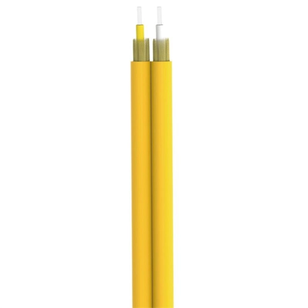
A Mode Conditioning Patch Cord (MCPC) is a specialized fiber patch cord designed to control the launch condition of light from a single-mode transmitter into a multimode fiber. Fiber optic cables primarily come in two types: Multimode Fiber (MMF): Has a larger core, allowing multiple light modes (paths) to travel. It's designed for short-distance, high-bandwidth applications within buildings or campuses. Common types are OM1, OM2, OM3, and OM4. Its primary purpose is to reduce differential mode delay (DMD) and prevent bandwidth limitation when legacy multimode. FS offers OM1 & OM2 mode conditioning fiber optic patch cables (MCP) in any connector & cable length, optimal for eliminating differential mode delay effects. This document describes the installation and use of the mode-conditioning patch cords listed in Table 1. 3z-compliant optical fiber assembly consisting of a single-mode fiber permanently coupled off-center to a 62. 5/125) fiber optic cable by offsetting the Singlemode Laser launch from the.
[PDF]
FC-FC patch cords have strictly overdefined precise tolerances between the cable, the optical source, the emitter and the detector that ensures reliable data transfer in high speed fiber networks. The most common choice of application of the FC-FC patch cord is in Video over Fiber Transmission Equipment. You can also use the FC-FC patch cord in many applications such as in data communications, telecommunications, measurement/test equipment, LAN cabinets and single-mode lasers. The FC connector itself is so defined under the IEC 61754-13 stan. With FC-FC fiber optic terminations, your connected device or devices are protected under the harsh and extreme environment situations such as those with high vibrations. OTSCABLE supplies FC-FC fiber optic cable assemblies, with single mode (9/125) and multimode (50/125 and 62.5/125) options. You can choose if it's for riser application or plenum connections or if you want it to be completely customized, you can contact us to know more about our OEM/ODM service for FC-FC patch cords.
[PDF]

Bend insensitive fiber patch cable is designed to transmit light with minimum loss even if they are bent beyond the bend radius. Fiber optic patch cords are often treated as low-risk consumables, yet a large percentage of optical link failures originate at the patch cord level. Unlike backbone cables, patch cords are frequently connected, disconnected, bent, and handled by technicians, making them the most vulnerable. The bend radius of fiber cables is critical for maintaining high performance and longevity. During installation under tension, maintain a minimum bend radius of 20 times the cable's outer diameter, while post-installation requires a minimum long-term bend radius of 10 times the cable diameter. Fiber optic cables are designed to withstand some bending, but excessive bends can physically damage the glass fiber or cause significant signal loss. That's why every fiber cable has a minimum bend radius specification provided by the manufacturer. The minimum bend radius defines the smallest. When fiber optic cables are bent more sharply than recommended, the internal fibers can break or develop micro-fractures, leading to: Reduced Signal Quality: Noticeable deterioration in signal transmission, including lower speeds and data loss, often results from bending-induced damage. As the bending becomes more acute, more light leaks out (shown in the picture below).
[PDF]

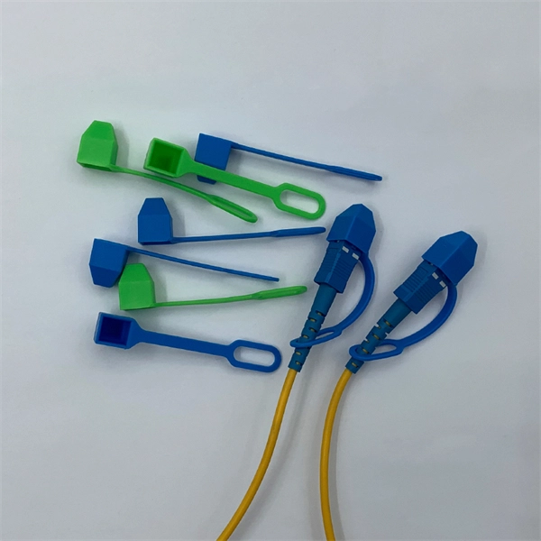
In this post, we'll walk you through practical tips, essential tools, common pitfalls, and the techniques that will help you get your fibre patch cable installations right the first time. Correct patch-cord installation is essential for maintaining low insertion loss, stable return loss, and long-term reliability in both indoor and outdoor fiber networks. Proper handling, routing, cleaning, bend-radius management, and connector alignment ensure that the optical link meets design. Proper connection of fiber optic cables is essential to harness these benefits fully, as even minor errors can lead to significant performance issues like signal loss. This guide addresses expert-certified best practices applied by professionals in the telecommunications, data. Yingda outlines the tools and materials needed to install fiber optic patch cords, as well as a complete step-by-step installation guide and important safety considerations to take. We will also tie this procedure back to the earlier discussion of multi-mode fiber types (OM1 to OM5) and connection. The Flex-Angle boot is designed to bend any angle or direction from straight to 90°. OMC flex angle boots for LC&SC fiber optic connectors are available on any single-mode or multimode patch cord. They are designed so the installer can pre-bend the boot into any direction or angle. Selecting the correct fibre patch lead is crucial for optimising signal performance and.
[PDF]

Multi-mode fiber optic patch cords utilize a larger core size, typically around 50-100 microns, allowing them to carry multiple modes of light. This design enables the transmission of data over relatively short distances with high bandwidth capabilities. A fiber-optic patch cord is a fiber-optic cable capped at each end with connectors that allow it to be rapidly and conveniently connected to telecommunication equipment. This is known as interconnect-style cabling. A fiber-optic patch cord is constructed from a core with a high refractive. These short fiber optic cords connect transceivers, switches, patch panels, and servers. Without them, even the best optical modules and switches cannot deliver performance. As data rates increase from 10G → 100G → 400G → 800G, patch cables must handle more bandwidth, more density, and stricter. Fiber optic patch cords, also known as fiber optic patch cables or fiber jumpers, are indispensable components in modern optical networks. They act as the critical link for interconnecting devices like optical switches, servers, and distribution frames. Understanding the various technical. Fiber patch cables, also called fiber-optic patch cords, are cables typically containing one or two optical fibers, which are equipped with standardized fiber connectors on both ends. The function of the fiber patch cord.
[PDF]

Use a fiber optic stripper to remove the protective jacket from the end of the fiber. Be careful not to nick or damage the fiber itself. This is an outdoor rated fiber that is very. Fiber patch cables can be used with many network devices, such as optical transceiver modules, fiber adapter panels, fiber cassettes, media converters, and other products having fiber optic interfaces. The actual steps may vary depending on the cable and/or connectors. Fiber optic cables are typically damaged in one of two ways: A premade fiber optic cable suffers connector damage when too. However, if the cap is too tight to pull using your finger, you can use a pair of soft-tipped tweezers to remove it gently. Step 2: Using your fingers or the tweezers, grasp the cap's edges. To strip and clean outdoor FO cable, you have to start with the outer jacket. Step 1: Mark the armor (if the cable has armor) with the tip of your knife to note a length sufficient to expose the cable's ripcord, being careful not to go through the armor and cut the ripcords. Step 2: Cut and remove. Gather the required tools before attempting to remove a fiber optic LC connector. A dust cap, a fiber optic connector cleaner, and a lint-free cloth are required. Examine the Connector You.
[PDF]

1000BASE-SX is a gigabit Ethernet standard over fiber optic for short reach. It is used for operating on multimode fiber with a short wavelength of 770 to 860 nanometers (typically 850nm). The “SX” stands for short reach over multimode fiber. 1000BASE-SX defines a maximum length of 220 meters for. What Is An Sx Sfp Module? The Ultimate Guide To 1G Transceivers (Sx Vs Lx Vs Sr) If you are buying fiber optic transceivers for a network upgrade, the alphabet soup of acronyms can be a nightmare. You see SX, LX, SR, LR. and they all look like the same little metal box. But choosing the wrong one. A Beginner's Guide: What is 1000BASE-SX, 1000BASE-LX & 1000BASE-ZX? Gigabit Ethernet (GbE) has gained significant popularity and is widely used in enterprise network backbones. It's defined by IEEE standards 802. These standards are vital for Ethernet's physical layer and. 1000Base-SX is a type of standard for implementing Gigabit Ethernet networks. The SX in 1000BaseSX stands for short, and it indicates that this version of Gigabit Ethernet is intended for use with short-wavelength transmissions over short cable runs of fiber-optic cabling. The application's nominal symbol rate is 1. 25 GBd per lane and the supported distance varies according to the type of multimode cable used. These modules convert electrical signals from.
[PDF]

Even when a network is designed correctly, real-world conditions—fiber handling, connector cleanliness, splices, environmental stress, and aging—can gradually increase attenuation or introduce reflections and interference. Fiber optic patch cords are often treated as low-risk consumables, yet a large percentage of optical link failures originate at the patch cord level. Unlike backbone cables, patch cords are frequently connected, disconnected, bent, and handled by technicians, making them the most vulnerable. Optical attenuation is the gradual loss of flux (light intensity) as an optical signal travels through a fiber. Measured in decibels (dB), it's the logarithmic ratio of the output power to the input power. Every network has a "loss budget". Field guide for diagnosing high fiber optic attenuation. Learn to use the OTDR to identify contamination, micro-bends, and poor splices, ensuring your 400G network links remain within budget. This article explains practical, engineering-focused ways to mitigate signal. This measurement helps determine the efficiency of a fiber optic system. Several factors contribute to signal attenuation. These include absorption, scattering, and bending losses. Each factor plays a significant role in the overall performance of a network. Whether you're a network engineer, IT manager, or service provider, understanding these challenges and how to address them is critical for maintaining high-performance, reliable.
[PDF]
Semi-automatic fiber-stripping machines enable precise and efficient processing of coated, buffered, and jacketed glass fibers. Designed for reliability and repeatability, these machines ensure high-quality stripping results for demanding fiber optic applications. Engineered for efficiency and accuracy, this model integrates both wire stripping and cable jacket splitting functions, making it an ideal solution for manufacturers and. 1. ST-3000T has multi-function, which includes stripping jacket, cutting aramid at the same time. It has high efficiency and save 30-50% labor cost of the process. It use original pneumatic part, original sliding toll, original PLC program to coordinate the control. The accuracy of repeat position. The smart automatic 3-in-1 function can realize the simultaneous completion for process of "Cable peeling - Kevlar shearing - Outer sheath splitting" at same by just one action. Universal for single & duplex optical cables, 1. High production. Fiber-Life Patch Cables deliver ultra-speed!#fibercable Fiber-Life RBTX-3000T Fiber Optic Cable Jacket Kevlar Stripping Machine offers exceptional efficiency in fiber optic cable processing, specifically designed for stripping, peeling, and removing Jacket and Kevlar from 2. 2mm, this machine enhances productivity with its advanced features and user-friendly design. Discover the CLX-RB05.
[PDF]
The new connection links Zambia's terrestrial fibre network to Mozambique's submarine cable infrastructure, providing the landlocked country with direct access to global internet gateways. The project was unveiled at the Chanida–Cassacatiza One. While submarine communications cables are used to connect countries and continents to the Internet, terrestrial fibre optic cables are used to extend this connectivity to landlocked countries or to urban centers within a country that has submarine cable access. In most of the world, a large number. The northern Mozambican port of Nacala has been linked to the world's largest submarine fibre-optic cable system to improve digital communications, enabling the telecommunications companyVodacom to offer its customers a direct international gateway for faster and more reliable internet services. Vodacom has landed the latest section of the 2Africa submarine cable in the city of Nacala in northern Mozambique. In a statement, the operator said that “2Africa”, considered the largest. TendersOnTime, the best online tenders portal, provides latest Mozambique Optical Fibre tenders, RFP, Bids and eprocurement notices from various states and counties in Mozambique. TendersOnTime, the most comprehensive database for Government Tenders and International Tenders; collects information.
[PDF]
In this comprehensive guide, we'll walk through the best practices for installing various types of fiber optic cable, from patch cords to distribution fiber, and provide practical tips to ensure a successful installation. Correct patch-cord installation is essential for maintaining low insertion loss, stable return loss, and long-term reliability in both indoor and outdoor fiber networks. Proper handling, routing, cleaning, bend-radius management, and connector alignment ensure that the optical link meets design. Proper installation and regular maintenance of fiber optic patch cords play a crucial role in achieving optimized network performance, preventing signal errors, and extending service life. This guide addresses expert-certified best practices applied by professionals in the telecommunications, data. Proper connection of fiber optic cables is essential to harness these benefits fully, as even minor errors can lead to significant performance issues like signal loss. Whether you're connecting a data center, a corporate network, or a high-density fiber infrastructure, correct installation methods are essential. Yingda. In today's high-performance networks, fiber optic patch cables are the lifelines that ensure smooth data flow across switches, servers, and routers. Even the most advanced optical transceivers can only perform at their peak when paired with properly installed, clean, and precisely managed fiber.
[PDF]
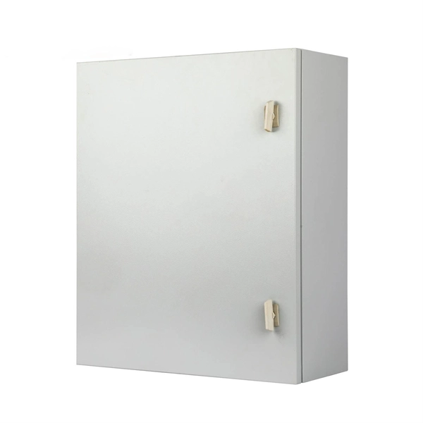
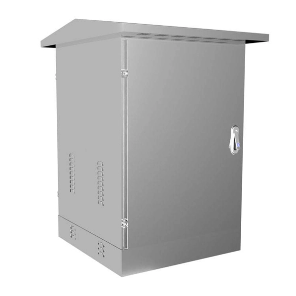
Fiber optic patch panels are enclosures that act as a distribution hub for fiber cable. A bulk (multi-strand) fiber cable enters the patch panel and then each fiber strand is separated into individual strands or pairs of strands. Fiber optic communications has been a rapidly expanding industry for the last 20 years. In its early years, it was mainly used for backhaul communications between large ISP's. But now fiber is widely used and can be found almost anywhere. It's probably in your ofice, on the telephone poles outside. A fiber patch panel is a mounted enclosure—either rack-mounted or wall-mounted—used to terminate, manage, and interconnect multiple fiber optic cables. It acts as a hub for organizing splices and patch cords, streamlining fiber management and preserving signal integrity. It provides a central point where incoming fiber cables can be connected to outgoing patch cords, making the network structured, accessible, and easy to maintain. This makes it easier to alter or troubleshoot the connections as they act as a central point where. Fiber patch panels play an increasingly important role in the optical fiber network due to the widespread use of high-density cabling systems in data centers. They are available in various fiber connector types, such as LC patch panel, SC patch panel and MTP patch panel. This article explores the structure, functionality, types, and benefits of fiber optic patch panels. What's the Fiber Optic Patch.
[PDF]

Fusion Splicer Settings – Must-Know for Fiber Technicians! 🔧 At D-TECH TRADING, we're demonstrating the essential Fusion Splicer settings that every fi. more. Auto Mode is the most intuitive and user-friendly splice mode. The fusion splicer automatically detects the fiber type, such as single-mode (SM), multimode (MM), or dispersion-shifted (DS) fibers, and adjusts parameters like arc power and heating time accordingly. Applications: Ideal for beginners. Page 1 Fusion Splicer 19R+/70R+ Quick Reference Guide Splice Operation • When splicing only standard SM fibers (ITU-T G. 652), “SM AUTO” mode is recommended. It also outlines instructions for keypad usage. st Instruction manual Fusion Splicer Please read this instruction manual carefully before operating the equipment. Adhere to all safety instructions and warnings contained in this manual. Keep this manual in a safe place. There is a change without a previous notice. We are not responsible for the. Fusion splicing is the bedrock of high-performance fiber optic networks, enabling seamless signal transmission through permanent, low-loss fiber joins. As a leading provider of fiber optic infrastructure, Weunion leverages cutting-edge tools like the AI9 and AI10 fusion splicers, paired with.
[PDF]
In this informative video, learn how to seamlessly integrate fiber optic cables with Power over Ethernet (PoE) systems for enhanced connectivity and performance. This installation guide focuses on what a patch panel does, patch panel installation basics, and how to connect patch panel to switch while keeping cabling clean and easy to manage. Switch: What's the Difference? Although a patch panel and a switch can look similar in a rack, they. Fiber patch panels are important components that are used to help organize and protect fiber optic cables. Connecting a fiber patch panel to a switch is a critical step in setting up a fiber optic network. Identify. If the PoE switch has SFP slot built-in, what you need is the SFP module installed in the slot. Firstly, Insert the SFP module into PoE switch's SFP slot. Discover the advantages of using fiber optic cables in conjunction with PoE and gain insights into the necessary components required for. If you have an existing patch panel the short answer to “can I just plug in a cable into the front of it” is yes. In comparison to wiring up individual networks, patch panels are much more efficient and can provide more reliable, faster connections. This article will.
[PDF]

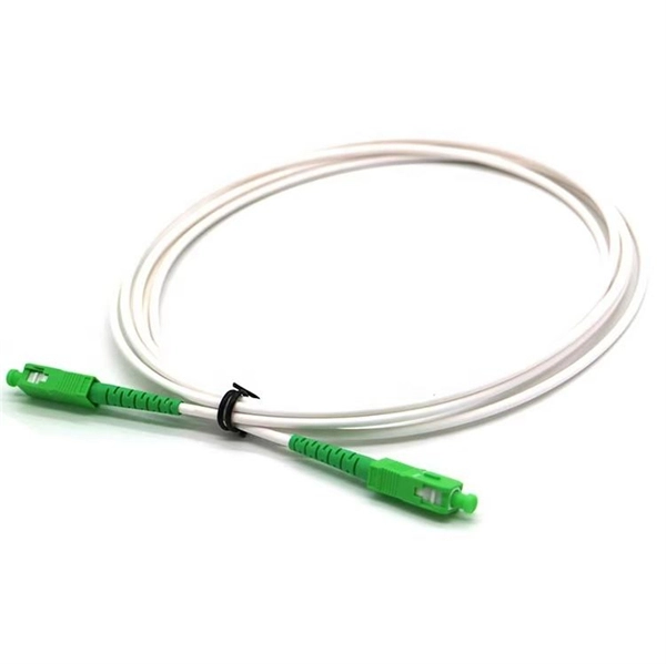
Connecting a multi-mode SFP to single-mode fiber creates a major signal mismatch. A small portion of the transmitted light gets captured. This leads to high attenuation and frequent link drops. I suggest you avoid such setups. Use them if essential and with proper mode. A Fiber Channel SFP is a specialized optical transceiver designed exclusively for Fiber Channel (FC) networks, enabling high-speed, low-latency, and lossless data transmission in Storage Area Network (SAN) environments. These transceivers comply with the ANSI INCITS 404-2005 Fiber Channel standard and IEEE 802. 3 for. There are two main types of fiber optic cables: single mode and multimode. Although they can do the same job in some instances, the different construction methods make each of them better suited to certain tasks and budgets. That makes picking between single mode and multimode fiber optic cables an. Single-mode (SMF) and multi-mode fiber (MMF) use different core sizes, sources and wavelengths. Understanding the compatibility constraints prevents costly downtime and troubleshooting. What Is the Difference Between Single Mode and Multimode Fiber? The main difference between these fiber options comes down to how light travels through. What is Single-mode SFP? Before we compare them, we need to know their brief definitions. A single-mode SFP is specially used with the 9/125µm single-mode fiber (SMF) but can not be used with multimode fiber cable.
[PDF]