Cable Trays* — Max two 24 in. (610 mm) wide by max 6 in. (151 mm) deep open-ladder cable tray with channel-shaped side rails formed of 0. 54 mm) thick aluminum or min 0. In practice, cable tray dimensions are a system of interrelated measurements —width, depth, length, and material thickness—that directly affect cable fill compliance, heat dissipation, structural loading, and long-term expandability. From an engineering standpoint, cable tray dimensions are not. Perforated Cable Tray System expertly constructed from high-grade stainless steel, offering exceptional durability and resistance to corrosion. With side height 100mm. A properly designed and installed cable tray system will provide. Studs — Wall framing to consist of wood studs or channel shaped steel studs. Wood studs to consist of nom 2 by 4 in. Additional studs shall be used to completely frame. Best Size: Here, deep trays (75mm to 150mm) are used since power cables are typically thick and heavy. Data cables, such as your Wi-Fi or computer ones, are extremely sensitive. They do not get hot; however, they do not like to hang or sag. In case a data cable folds in an excessive manner, the. ect the minimum bend ra-dius for cables as they exit the bottom of the cable tray. A rung spacing of 6 to 9 inches (150 to 230 mm) is preferable when the cable tray cont d for instrumentation and control applications that require additional protec eferred to support and protect numerous small.
[PDF]
This article shows you how to create and configure your virtual switch using Hyper-V Manager or PowerShell. A virtual switch allows virtual machines created on Hyper-V hosts to communicate with other co.
[PDF]
In a typical enterprise network architecture, the access layer switch is the first point of contact between end-user devices and the rest of the network. These switches connect endpoints such as PCs, printers, VoIP phones, and wireless access points, enabling user traffic to enter the LAN. It assists mainly in the switching of incoming and outgoing data packets to the right destination, as specified in MAC. In this layer, the layer 2 switches are installed to distribute the data packets to the addressed group of access devices. The layer 2 switches prevent over-crowding of data packets in transmission links and access devices. Wireless access points are also connected here and provide further access. FortiSwitch units distribute the ports to plugs. This layer serves as the network's outermost boundary and the gateway through which all data must pass. This layer is primarily composed of devices like access switches and wireless access points.
[PDF]
A 3 × 3 all-optical interconnecting switch using three quantum dot semiconductor optical amplifier assisted Mach-Zehnder interferometers (QDSOA-MZI) has been designed. It can transmit input data to any outpu.
[PDF]
This page contains wiring diagrams for household light switches and includes: a switch loop, single-pole switches, light dimmer, and a few choices for wiring an outlet/switch combo device. Check permit requirements before beginning electrical work. How to read these diagrams. Also included are. A house switch, also known as a light switch or electrical switch, is a device that is used to control the flow of electricity to a particular circuit in a house. It is a simple device that can be found in almost every room of a house and is used to turn lights on and off. and Be Sure to Subscribe! Make sure the circuit power has been turned off, and mark the circuit breaker or fuse to indicate that work is. The following house electrical wiring diagrams will show almost all the kinds of electrical wiring connections that serve the functions you need at a variety of outlet, light, and switch boxes. For help understanding them, be sure to open the Explanation page. This panel is the central hub that distributes electricity throughout the house. It is usually located in a basement, utility room, or garage. Understanding the wiring diagram of a typical house can help you troubleshoot any electrical problems and make upgrades or repairs with confidence.
[PDF]
Introduces basic principles and application scenarios of the wired and wireless convergence feature supported by S series switches. Online view is not supported. Switch stacking is the process of combining multiple switches into a logical device that participates in data forwarding as a whole, in order to expand the number of ports, simplify networking, increase reliability, and extend the system's processing power and bandwidth. Moduletek Labs takes Huawei. Unless otherwise specified in the contract, all statements, information, and recommendations in this document are provided "AS IS" without warranties, guarantees or representations of any kind, either express or implied. effort has been made in the preparation of this document to ensure accuracy of. This document describes the best practices for stack deployment, including device selection, deployment, networking deployment, stack setup failures, and reliability. As flagship core switches in Huawei's CloudCampus portfolio, this series enables you to. The Huawei S2700 Series switches are a versatile collection of enterprise-level managed Ethernet switches, specifically designed to meet the needs of small and medium-sized businesses (SMBs). Featuring robust performance, simplified management, and advanced Layer 2 switching capabilities, the S2700.
[PDF]

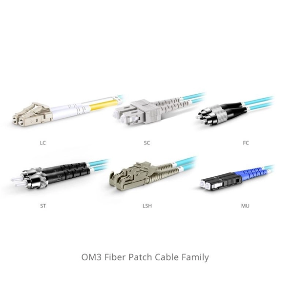
Most modern fiber-enabled network switches require an SFP transceiver module featuring a duplex (two strand) multimode OM3 or duplex single mode OS2 connection with LC connectors. Direct attach cables with pre-terminated SFP connections may also be used. Download the. In addition, fiber cables can transmit data over several kilometers without signal degradation, making them ideal for connecting switches in large campus networks and between different buildings. As they do not emit electromagnetic signals, they're difficult to tap and secure against eavesdropping. Fiber optic cabling is increasingly used to connect network switches and other datacom equipment, especially in long-distance and mission-critical applications. Fiber provides: Increased internet signal bandwidth. The USB console port uses a USB Type A to 5-pin mini-Type B cable, shown in Figure 55 on page 85. The USB Type A-to-USB mini-Type B cable is not. Connecting a switch to a fiber optic network involves several steps and requires specific equipment to ensure a successful and efficient connection. This guide will. Many people ask the same question: Can you use a fiber optic cable with an RJ45 port? The short answer is no - RJ45 connectors are designed for electrical Ethernet signals, while fiber optics transmit light pulses through glass or plastic. However, modern networks often combine both technologies. Fiber optic technology has revolutionized data transmission, offering unparalleled speed and.
[PDF]

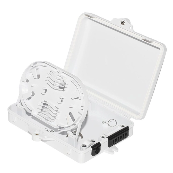
Fiber splitters serve as essential components in optical networks. These devices divide an optical signal from a single input into multiple outputs. This process enables efficient signal distribution across various network points. Fiber splitters function without the need for external. In the intricate web of modern fiber optic networks, where data travels at the speed of light across continents, fiber optic splitters play a silent yet pivotal role. These unassuming devices enable a single optical signal to be divided into multiple paths, making them indispensable for sharing. A fiber splitter, also known as a beam splitter, is a passive optical device that splits an optical signal into multiple signals. By dividing a single optical signal into multiple signals, fiber. Fiber optic splitters are vital in modern communication networks. Fiber optic splitters, such as plcsplitter and fbt splitters, are crucial in maintaining signal integrity, with considerations for IL (Insertion Loss) and RL (Return Loss). They are integral components in the world of telecommunication and data networking, crucial to maintaining reliable and efficient communication infrastructures. There are two primary.
[PDF]
Switches in this layer are called access switches. In other words, an access switch forwards traffic between connected devices and the rest of the LAN. The following image shows a network that contains. The access layer is where endpoints (such as phones, laptops, video-conferencing sets, printers, IoT sensors, IP cameras, and servers) are primarily connecting to the network. FortiSwitch units distribute the ports to plugs. Access layer switches are primarily deployed in Layer 2 mode in the data center. A Layer 2 access topology provides the following unique capabilities required in the data center: VLAN extension—The Layer 2 access topology provides the flexibility to extend VLANs between switches that are connected. It contains three layers: core, distribution, and access. The core layer is the backbone of the network. It provides a high-speed connection between different distribution layer devices. The layer 2 switches collect the data from core switches, identify the type of data packet and the address of the access device. Further, the data packets are forwarded to the addressed group of.
[PDF]
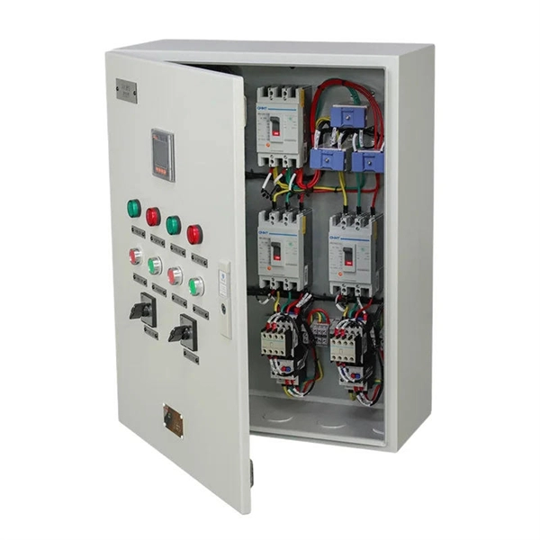
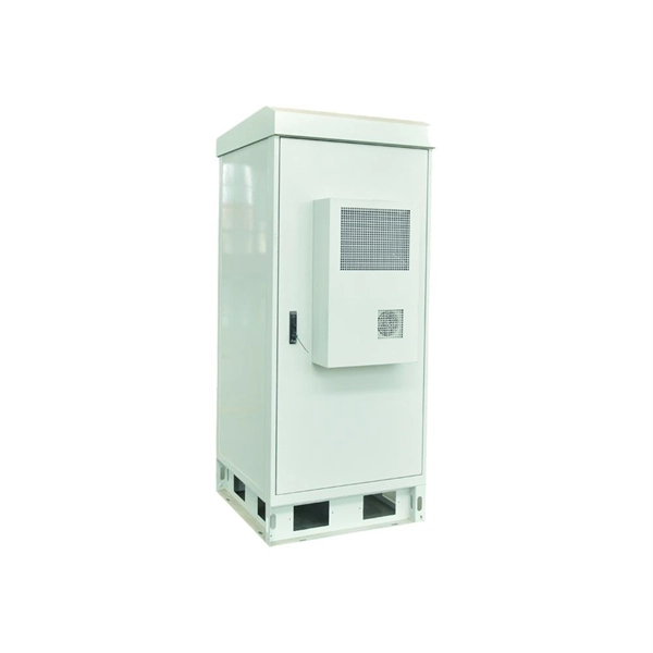
Inside the distribution box, you'll also find switches and indicators. The switches are used to control the circuits—turning them on or off as needed. A distribution box, also known as a distribution board, electrical panel, or breaker box, is an enclosure that houses electrical components responsible for distributing electricity throughout a building. It receives power from the main electrical supply and divides it into separate circuits, each. Messy distribution boxes are dangerous and very hard to fix. This guide shows you how to organize circuit breaker wiring properly. You will learn to build a safe, efficient, and professional electrical system today. Indicators, like LED lights, show the. A distribution box uses MCBs, RCDs, and busbars to protect circuits, prevent shocks, and ensure safe power distribution in homes and buildings. It acts as the central point where electricity distribution is managed inside a building. These diagrams provide a visual representation of how the electrical circuits are connected, allowing electricians and homeowners to troubleshoot issues.
[PDF]
A switch must use optical or copper modules that have been certified for use on Huawei switches. Non-certified optical or copper modules cannot ensure transmission reliability and may affect service stability. Huawei is not liable for any problem caused by the use of non-certified optical or copper. The purchased products, services and features are stipulated by the contract made between Huawei and the customer. Unless otherwise specified in the contract, all. Compatible SFP transceiver supports up to 80km link lengths over single-mode fiber (SMF) using a wavelength of 1550nm via an LC connector. Each SFP transceiver module is individually tested to be used on a series of Cisco switches, routers, servers, network interface card (NICs) etc. It has minimum guaranteed optical budget of 25 dB, with in most cases is enough to reach about 40 km distance. However, distance is. We supply professional-grade optical networking components for ISPs, enterprises, data centers, and network installers across Kenya, and the Authentic Huawei 155M-1310nm-15km-SM-eSFP is a proven and trusted solution for reliable fiber connectivity. Huawei is globally recognized for its advanced. Introducing the Huawei OSC015B01, a cutting-edge optical transceiver designed for high efficiency and unparalleled performance. This eSFP module, with its Tx 1310nm/Rx 1550nm wavelength capabilities, is engineered for 155M operations, making it ideal for a variety of network enhancement tasks.
[PDF]
These switches are vital for Chile's mining and solar industries due to their small size and high reliability in extreme conditions. This guide will help you understand why these compact solutions are the new standard for the Chilean power grid in 2026. Compact load break switches in Chile are specialized electrical devices used to safely disconnect power under load. They must comply with SEC standards and IEC 60947. What Is a Compact Load Break Switch? A compact load break switch. E-Energy specializes in developing projects and solutions in SCADA, control, communications, and electrical protections for generation plants and substations. Their scope includes electrical and mechanical maintenance of various assets, such as switchgear and protection systems, ensuring compliance.
[PDF]
They support link aggregation protocols such as Link Aggregation Control Protocol (LACP) and Static Link Aggregation, which allow multiple physical links to be combined into a single logical connection. This enhances bandwidth, redundancy, and ensures failover capability in case of a. The three layers of a traditional three-layer network design are the core layer, aggregation layer, and access layer. Together, these layers can offer consumers a network that is safe, reliable, and affordable. As the physical part of the aggregation layer, aggregation switches typically play a. An aggregate switch is a high-capacity network switch that consolidates connections from multiple access switches, acting as a central point for managing network traffic and providing enhanced bandwidth capabilities. It is essential for larger networks requiring efficient data flow. This article looks at what each such tool does, compares how they differ from each other, and offers suggestions as to what sort of network each. The aggregation (sometimes also called distribution) layer is a real crossroad. Its primary goal is to increase network scalability by providing a single place to interconnect multiple access switches and the core layer.
[PDF]
How to connect multiple switches in a network with clear steps and tips for effective setup and configuration. Switches operate at the data link layer of the OSI model, forwarding packets of data between devices based on their MAC addresses. Switches come in various shapes and sizes, ranging. Cascading switches refers to the process of connecting multiple switches together in a series, effectively expanding the network's capacity and reach. This hierarchical connection allows for efficient and seamless communication between devices, regardless of their physical location within the. In the world of networking, Ethernet switches are integral components that provide the necessary interconnects for our devices. Sometimes, one switch is not enough to meet our needs, whether in terms of port number, specific functionalities, or both. Essentially, a LAN switch sets up a series of temporary networks that span only the two devices currently exchanging data. Depending on the configuration, connecting multiple switches can also. When one switch cannot meet the number of ports and a specific functional requirement, usually users will connect multiple Ethernet switches together, so how to connect multiple Ethernet switches together during network deployment? Three common types of connections are currently available:.
[PDF]
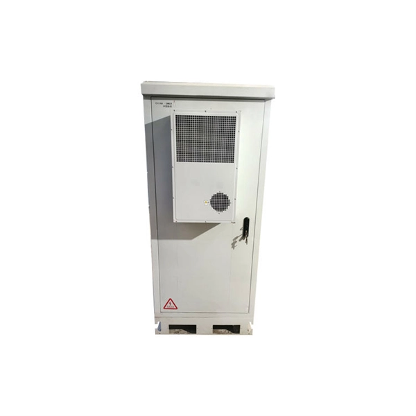
In industrial-grade switch applications, redundant power supply (RPS) has become a critical technology for ensuring network stability. Particularly in harsh environments like photovoltaic plants and coal mining sites, power failures can lead to catastrophic consequences. This article provides. A power redundancy design means that a network device can be connected to two power sources simultaneously. In this way, if one power source fails or loses power, the other can continue supplying power to the device, ensuring uninterrupted operation. This redundancy helps maintain network. Moxa provides a wide range of industrial Ethernet switches that feature industrial-grade reliability, network redundancy, strengthened security, easy management, and competitive price-to-performance ratios. Our comprehensive portfolio includes unmanaged switches, managed switches, PoE switches. One critical factor is power stability—an unexpected power failure can disrupt an entire switch, interrupt communication, and cause costly downtime or data loss. This article explores the importance of power redundancy, how it enhances system reliability, and various methods to achieve it, particularly. Extreme Industrial Switches are a family of ruggedized Layer 2 switches designed to operate under harsh environments and extended temperature conditions. They provide continuous uptime, manageability, and operational efficiency. With flexible PoE options of IEEE 802.
[PDF]