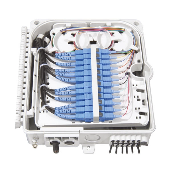
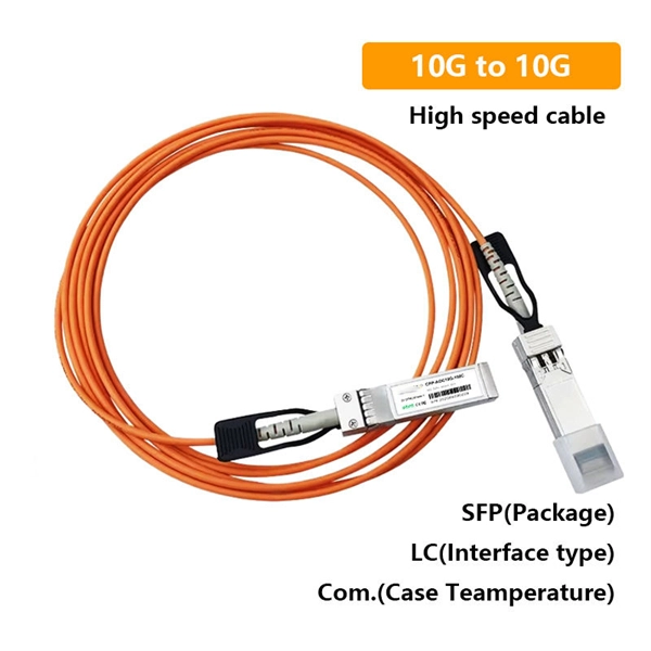
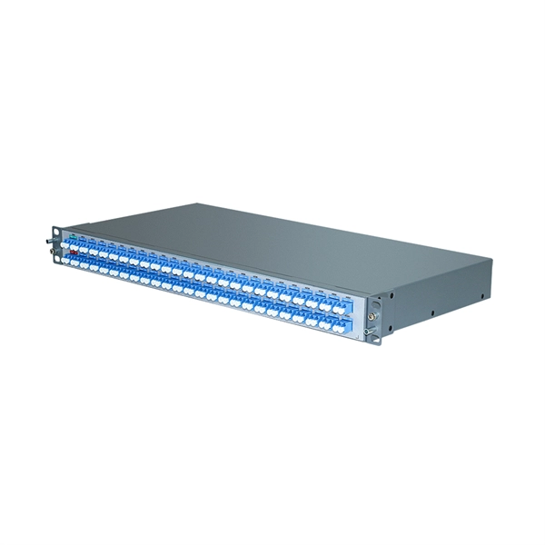
Most SFP fiber optic modules use LC connectors, while SC connectors are mainly found in legacy networks and MPO/MTP connectors are used for high-density cabling rather than directly on standard SFP modules. While the small size of fibre optic connectors does not mean they play a minor role, the type of connector you use affects the overall efficiency of light transmission across the fibre network. Of the more than a dozen types of fibre-optic connectors available, the four most commonly used today are. Fiber optic connectors are the unsung heroes of modern networking. They are small, often overlooked components, yet they are essential for ensuring high-speed, low-loss, and reliable optical transmission. This connector landscape reflects how modern SFP deployments prioritize port density and. A fiber optic connector is a mechanical device used to align and join optical fibers, enabling light to pass through with minimal loss. Unlike fiber splicing, which is permanent, connectors allow for easy connection and disconnection of cables, making them ideal for maintenance and flexibility in. Fiber connector types LC, SC, FC, ST, MTP, and MPO are widely used in past and present. What are the differences between them? Who is the most popular one? Find the answer in the article. As a leading provider of fiber optic solutions, Weunion understands the critical role of connectors in modern networks.
[PDF]
5″ hard drive with a storage capacity of 80GB and featuring a IDE interface. ST380011A Seagate Barracuda 80GB 7200RPM ATA/EIDE 2MB Cache 3. 5-inch Low Profile (1. All information about the Seagate ST380011A hard disk drive: technical parameters, failure. 8-Mbyte buffer on: ST3200822A, ST3160023A, ST3120026A, and ST380013A High instantaneous (burst) data transfer rates (up to 100 Mbytes per second) using Ultra DMA mode 5. Giant magnetoresistive (GMR) recording heads and EPRML technology, which provide the drives with increased areal density. Manuals and User Guides for Seagate Barracuda 7200. 7 ST380011A Drive manuals available for free PDF download: Product Manual, Installation Manual Figure 3. Breather Filter Hole Location Figure 4. Ultra ATA. 1. 7 Plus • ST3160023A • ST3120026A • ST380013A Barracuda 7200. 7 • ST3160021A • ST3120022A • ST380011A • ST360014A • ST340014A These. HITACHI HDS721032DLE630 (320 GB S-ATA Gen3) SAMSUNG HS10XJC (100 GB IDE) SEAGATE ST9250612NS (250 GB S-ATA Gen3) Device manufacturers may change any parameters without prior notice. There is no warranty that the information listed here is complete and accurate. If you encounter any improper value. Our goal is to provide you with a quick access to the content of the user manual for Seagate Barracuda ST380011A. If looking through the.
[PDF]
Connect the fiber optic cable: Attach the fiber optic cable's connector to the transceiver module on the switch. Make sure the connector type (e., SC, LC) matches the transceiver module. Fiber optic cabling is increasingly used to connect network switches and other datacom equipment, especially in long-distance and mission-critical applications. Fiber provides: Increased internet signal bandwidth. Most modern fiber-enabled network switches require an SFP transceiver module. This document describes how to troubleshoot fiber optic interfaces by addressing some of the fiber optic module and cabling specifications. There are no specific requirements for this document. The information in this document is based on all Catalyst 9000 Series switches. This includes Doppler. Connecting a switch to a fiber optic network involves several steps and requires specific equipment to ensure a successful and efficient connection. If you're looking to learn how to configure fiber optics on a Cisco switch, it's important to first configure the switch settings so it's ready for fiber optics. Fiber optic switches utilize. Other than entry level network switches, most of today's network switches include one or more GiBC (Gigabit Converter) or SFP (Small Form-factor Pluggable) slots. SFP modules insert into these slots and and require two strands of fiber, typically duplex Using multi mode fiber (for runs under 1000.
[PDF]
For a basic plastic D-box, expect $25-$60 per unit, with installed costs typically $150-$400 depending on site access and labor rates. Heavier-duty or multi-zone configurations can push total to $600-$1,000 for the box and labor, while complex installations or off-grid sites. Buyers typically pay a wide range for septic distribution box replacement, with cost driven by box material, accessibility, and local permitting. This guide outlines typical price ranges, how costs break down, and regional differences to help homeowners budget accurately. The price is driven by box type, piping connections, and the need for trenching or backfilling. This guide provides a clear cost range in USD with practical budgeting tips and per-unit. Homeowners often pay for a distribution box (D-box) as part of a septic system upgrade or replacement. Cost ranges reflect box price plus. Distribution box cost encompasses various factors that influence the overall investment in electrical distribution systems. The cost is driven by box size, material, and installation requirements, with price ranges reflecting basic plastic units up to heavier-duty or re-locatable options. The following. While distribution box prices depend heavily on capacity and features, we've tracked emerging patterns. Expect these price points when budgeting for 2025 installations: Quality power cables make or break your electrical system. Modern copper-aluminum hybrids offer conductivity at lower cost while.
[PDF]
Learn about the two main types of fiber optic couplers: fused and planar. Fused couplers are cheap and work well. Pick the port setup that fits your needs. When it comes to proper fiber optic coupler selection, you will have to consider the effectiveness of the application in splitting and distributing optical signals without losing or interrupting the signal. If you choose poorly, the server signal will not be strong, there will be delays in. Fiber optic adapters, also known as couplers, play a crucial role in fiber optic networks by providing a connection point between two fiber optic connectors. They enable seamless and reliable optical signal transmission between different fiber optic cables, connectors, or devices. In this tutorial. This comprehensive guide explains what fiber optic adapters are, their common types, key selection criteria, cleaning best practices, frequently asked questions, and how customized connector solutions can benefit B2B projects in telecommunications, data centers, and industrial networks. What Is a. This small device connects or joins optical fibers together. It helps networks grow and change when needed. It provides an objective comparison to help you identify the best solutions for your networking needs. Unlike fiber splicing, which is permanent, connectors allow for easy connection and disconnection of cables, making them ideal for maintenance and flexibility in.
[PDF]

This video shows real on-site footage of electrical installation, demonstrating safe and standardized wiring methods used by professionals. more Learn how to wire a distribution box step by step! This video shows real on-site footage of. Material preparation: Prepare the required circuit breakers, wires, wiring ties and other materials, and ensure that they meet the design drawings and installation requirements. Location determination: Determine the installation position of the circuit breaker according to the position of the. Learn how to install a distribution box safely and correctly. Covers wiring, placement, standards, and expert tips for a compliant setup. A distribution box is the heart of any electrical system. It takes the incoming power and safely distributes it to different circuits throughout your building. And all the switching and protective devices are installed in the distribution box. Single Phase Distribution Box generally consists of Double Pole MCBs, Single Pole MCBs, and RCCBs. So here's what you need to know about wiring distribution panels, to make sure yours operates exactly as needed and as expected. Each circuit supplies a specific load, whether it's going to. Explosion-proof distribution boxes, vital terminal distribution equipment in power systems, play a crucial role in controlling and protecting industrial electricity in hazardous environments.
[PDF]
Each type is optimized for specific uses and includes features suitable for different devices. They use precision ferrules and alignment sleeves to connect two fiber cores, maintaining light transmission efficiency. Fiber connector types LC, SC, FC, ST, MTP, and MPO are widely used in past and present. What are the differences between them? Who is the most popular one? Find the answer in the article. What is a Fiber Connector? The optical fiber connector is a kind of detachable passive optical component used. A fiber optic connector is a mechanical device used to align and join optical fibers, enabling light to pass through with minimal loss. This connector landscape reflects how modern SFP deployments prioritize port density and. Fiber optic connectors are the unsung heroes of modern networking. They are small, often overlooked components, yet they are essential for ensuring high-speed, low-loss, and reliable optical transmission. An optical fiber connector enables quicker connection and disconnection than splicing. Because of this, it's no surprise that fiber optic connectors are in high demand.
[PDF]

Use the SWD or JTAG interface to connect the ST-Link v2 to the STM32 microcontroller. Download and install STM32CubeIDE or another compatible IDE. Install the ST-Link USB driver (available on the STMicroelectronics. The ST-LINK/V2 is an in-circuit debugger/programmer for the STM8 and STM32 microcontrollers. The single wire interface module (SWIM) and the JTAG/serial wire debugging (SWD) interfaces facilitate communication with any STM8 or STM32 microcontroller operating on an application board. ATOLLIC, IAR and KEIL Integrated Development Environments for. How do you use SWD (Serial Wire Debug) for debugging STM32? - HackMD Using SWD (Serial Wire Debug) for debugging STM32 microcontrollers is a powerful way to monitor and control code execution, inspect registers, and analyze faults. Here's a step-by-step guide to set up and use SWD effectively: 1. In addition. This small guide will explain how to connect your debugger to your development board. There are two commonly used connectors which expose only the SWD (Serial Wire Debug) interface or the full JTAG interface. If you are using one of ST's official Nucleo or Discovery boards, you do not have to. To upload a program to a chip from Thomson Semiconductor you need an ST-Link programmer device to connect your PC. Thompson sells branded programmers, adaptors and cables. We'll use an inexpensive ST-LinkV2. They look like AVR programmers but you need to read the pinouts on the side.
[PDF]