5″ hard drive with a storage capacity of 80GB and featuring a IDE interface. ST380011A Seagate Barracuda 80GB 7200RPM ATA/EIDE 2MB Cache 3. 5-inch Low Profile (1. All information about the Seagate ST380011A hard disk drive: technical parameters, failure. 8-Mbyte buffer on: ST3200822A, ST3160023A, ST3120026A, and ST380013A High instantaneous (burst) data transfer rates (up to 100 Mbytes per second) using Ultra DMA mode 5. Giant magnetoresistive (GMR) recording heads and EPRML technology, which provide the drives with increased areal density. Manuals and User Guides for Seagate Barracuda 7200. 7 ST380011A Drive manuals available for free PDF download: Product Manual, Installation Manual Figure 3. Breather Filter Hole Location Figure 4. Ultra ATA. 1. 7 Plus • ST3160023A • ST3120026A • ST380013A Barracuda 7200. 7 • ST3160021A • ST3120022A • ST380011A • ST360014A • ST340014A These. HITACHI HDS721032DLE630 (320 GB S-ATA Gen3) SAMSUNG HS10XJC (100 GB IDE) SEAGATE ST9250612NS (250 GB S-ATA Gen3) Device manufacturers may change any parameters without prior notice. There is no warranty that the information listed here is complete and accurate. If you encounter any improper value. Our goal is to provide you with a quick access to the content of the user manual for Seagate Barracuda ST380011A. If looking through the.
[PDF]

An Optical Splitter, also known as a beam splitter, is a passive optical device that divides a single input optical signal into two or more output signals. Conversely, it can also combine multiple signals into one. Knowing the difference between a splitter and an optical coupler helps you build better networks. You make your network work better when you pick the right device for each job. You can connect many users to one port with 1:n or 2:n splitters. By dividing a single optical signal from a central Optical Line Terminal (OLT) into multiple outputs for Optical Network Terminals (ONTs) at users' homes, splitters eliminate the need for dedicated fibers to each residence—slashing infrastructure costs while scaling network reach. This guide. In a Passive Optical Network (PON), a single optical fiber carries massive amounts of data using light. Signal Input: The fiber splitter receives the optical signal from the upstream network node and enters the splitter through the input fiber. Signal Distribution: Inside the splitter, according to the design structure and different. Splitters are passive optical devices that divide or combine optical signals, and they come in various types, including power splitters, uneven splitters, and wavelength-division multiplexing (WDM) splitters. Each type serves specific applications, enabling efficient use of optical infrastructure.
[PDF]

A ladder type cable tray tee is a fitting used to create a branch in a cable tray system, allowing cables to be routed in three directions. Its "T" shape provides a secure and efficient way to split cables from a main tray into two separate paths, ensuring organized and flexible. A cable tray tee and tee cover are components used in cable management systems to support and protect electrical and data cables. Here's a brief explanation of each:. Rigid steel cable tray tee fitting with zero tangent, safety bottom, and full accessory support. ventilation to heat producing cable such as power communication and other with the same or different width of the cable run. All fittings are available in sizes and types corresponding to the straight cable tray sections. These fitting are including: elbow, horizontal cross, vertical inside. NOTE : Equal or un equal tees can be supplied. When ordering state widths W1xW2xW3.. Office: 147/22 Nguyen Sy Sach Street, 15 Ward, Tân Binh Dist, HCMC,VN. Is it possible to connect 2 cabletrays with a "branch piece (left picture)" instead of a "tee (right picture)". The tee has 3 connectors, the branch piece only has 1 connector. I would like to ajust the "Type properties -> Fittings -> Tee" with the branch family, but can't get it accomplished.
[PDF]

Cable Trays* — Max two 24 in. (610 mm) wide by max 6 in. (151 mm) deep open-ladder cable tray with channel-shaped side rails formed of 0. 54 mm) thick aluminum or min 0. In practice, cable tray dimensions are a system of interrelated measurements —width, depth, length, and material thickness—that directly affect cable fill compliance, heat dissipation, structural loading, and long-term expandability. From an engineering standpoint, cable tray dimensions are not. Perforated Cable Tray System expertly constructed from high-grade stainless steel, offering exceptional durability and resistance to corrosion. With side height 100mm. A properly designed and installed cable tray system will provide. Studs — Wall framing to consist of wood studs or channel shaped steel studs. Wood studs to consist of nom 2 by 4 in. Additional studs shall be used to completely frame. Best Size: Here, deep trays (75mm to 150mm) are used since power cables are typically thick and heavy. Data cables, such as your Wi-Fi or computer ones, are extremely sensitive. They do not get hot; however, they do not like to hang or sag. In case a data cable folds in an excessive manner, the. ect the minimum bend ra-dius for cables as they exit the bottom of the cable tray. A rung spacing of 6 to 9 inches (150 to 230 mm) is preferable when the cable tray cont d for instrumentation and control applications that require additional protec eferred to support and protect numerous small.
[PDF]
It can take primary power from a single source and then divides it among various secondary circuits. This process streamlines the wiring setup, making it easier to handle complex electrical configurations within an electrical panel. A distribution boxes is an essential device that manages the safe and efficient flow of electrical power throughout different areas of a building or facility. It is commonly used in homes, offices, and industrial settings to control and protect electrical circuits. Today, electrical systems are essential for homes and industries. Through its design and. A power distribution box is a key part of any electrical system. Without it, managing power would be messy, unsafe, and inefficient. At the heart of this network lies a power distribution box, the component responsible for dividing and controlling electricity as it moves from the main source to multiple end-use circuits.
[PDF]
There are porcelain, high-voltage bushings on the cover connected to the primary line. Disconnecting switches or plug connectors shall be installed to permit the disconnection of all ungrounded conductors of each temporary circuit. All lamps for general illumination shall be protected from accidental contact or breakage. Metal-case sockets shall be grounded. Temporary lights shall. There are three main types of electrical switchgear: low-voltage (LV), medium-voltage (MV), and high-voltage (HV). Low-voltage switchgear is a common type of electrical switchgear used in various industries to regulate systems up to 1kV. It controls power flow and isolates electrical equipment, and it acts as a central hub. Recent studies indicate that up to 70% of electrical distribution system failures originate from. High-voltage switchgear is are essential electrical product used across power generation, transmission, distribution, conversion, and consumption. They manage switching, control, and protection functions for voltages from 3. High voltage switches are specialized devices designed to operate under elevated voltages, typically above. High Voltage Switchgear (HV/HT), often referred to as HV (High Voltage) or HT (High Tension) switchgear, is a vital part of modern power systems. You'll find it in power plants, substations.
[PDF]
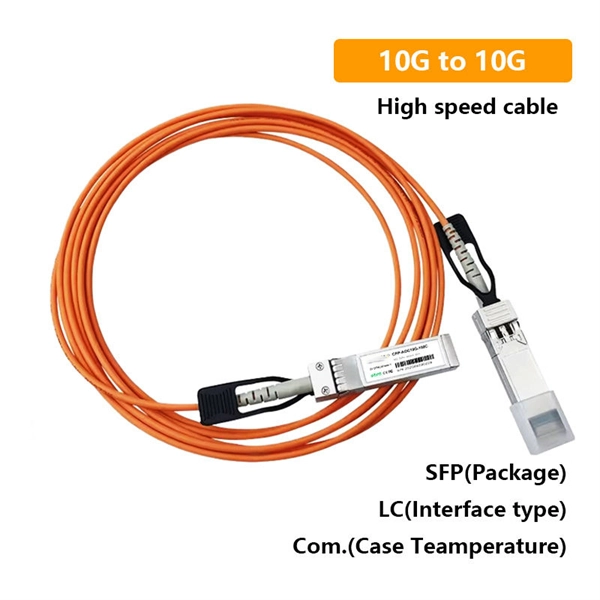
Fiber optic patch cabling is part of a fiber optic network construction, so the important choice is whether to use multimode patch cords or single mode patch cords. These patch cords aim to achieve the same goal of transmitting optical signals by the means of the construction, performance, and. Fiber optic patch cords, also known as fiber optic patch cables or fiber jumpers, are indispensable components in modern optical networks. They act as the critical link for interconnecting devices like optical switches, servers, and distribution frames. Understanding the various technical. This guide explains what fiber patch cables are, their types, connector standards, where they are used, and how to choose the right one for your data center. It is designed for flexible. But believe it or not, it's very possible that single mode fiber cables are the best option for you. While it is true that multi mode fiber optic cords are better at handling a heavier load than single mode cables, especially where a complex data network is involved, there are some situations where. When it comes to fiber optic patch cords, two primary types are single-mode and multi-mode. Single-mode fibers are designed to carry a single mode of light, allowing for higher bandwidth and longer transmission distances compared to multi-mode fibers. Singlemode fiber optic patch cables support high-speed networks up to 50 times farther than.
[PDF]

While nonarmored fiber optic cables don't require grounding due to their nonconductive properties, grounding is crucial when using armored fiber optic cables. Therefore, it is important to build a lightning protection system for fiber optic cables. How to Protect Fiber Optic Cable From Lightning? The major purpose of lightning protection systems is to conduct the high current lightning discharges safely into the Earth/ground. There are two main lightning. Fiber optic cable transmits data as light through glass or plastic strands, which means the fiber core itself carries no electrical current and requires no grounding. However, this does not mean every fiber optic installation is exempt from grounding requirements. Lightning-induced surges can travel through power lines, telecommunication lines, or nearby metallic structures and pose a. There are two main lightning protection grounding solutions in fiber networks, namely intermediate grounding and terminal grounding. These solutions use two ways of grounding for optical cable links both in domestic and foreign standards. However, because fiber optic cable has strengthened core, especially the direct-buried fiber optic cable has armoring layer.
[PDF]
When the optical switch module's switching interfaces are all busy or an optical signal needs signal regeneration through an OEO conversion process, the electronic module is used. In modern optical transport networks, optical cross‑connect (OXC) devices are essential for high-speed, flexible signal routing. An OXC switches optical signals between fiber inputs and outputs without converting them to electrical signals, enabling true all-optical routing. In the 1980s, when transmission speeds supported by optical fibers increased from 45 Mbit/s to 2. In essence, an OXC uses photonic switching fabric to route wavelength channels from any incoming fiber to any outgoing fiber. OXC (optical cross-connect) is an evolved version of ROADM (Reconfigurable Optical Add-Drop Multiplexer). As the core switching unit of the optical network, the scalability and economic efficiency of the optical cross-connect (OXC) not only determine the flexibility of the network topology, but. Vendors such as LINK-PP provide comprehensive transceiver and interconnect solutions that ensure OCS architectures perform at their highest potential. This article explores OCS fundamentals, its benefits, use cases, and how LINK-PP optical module solutions complement these networks. Compared with traditional ROADM based on separate boards and inter-board fiber patch cords, OXC uses integrated interconnections to build an all-optical switching resource pool, achieving highly integrated, fiber.
[PDF]
