These two categories define how light travels through the fiber core: Transmits a single light mode; very low attenuation; supports long-distance transmission up to 100 km or more. Transmits multiple light modes; higher dispersion; best for shorter distances. The most common distinction is between single mode vs multi mode fiber optic cable. There are many classifications of optical cables, due to the installation environment. It has stronger pressure resistance, corrosion resistance, greater tensile. In the landscape of network infrastructure, three primary cable categories dominate connectivity: twisted-pair copper cables, coaxial cables, and fiber optic cables. While copper-based solutions (such as Cat5e/Cat6 for twisted pair or RG-6 for coaxial) have long served as workhorses for local and. We'll cover single mode, multimode, and armored fiber cables below. Single mode fiber optic cable is made up of a small diameter glass or plastic core surrounded by cladding, which is a layer of reflective material. This small diameter core, typically around 9 microns in diameter, allows only one. There are two main types of fiber optic cables: single mode and multimode. Although they can do the same job in some instances, the different construction methods make each of them better suited to certain tasks and budgets.
[PDF]
Fiber testing is the process of verifying the performance of optical fiber cabling. This process includes a range of tests and measurements such as insertion loss, optical return loss, and fiber length. It encompass.
[PDF]
It emphasizes the importance of considering mechanical and environmental aspects, referring to the IEC 60794-2 series for technical specifications. The document details the characteristics of optical fibers and cables, including transmission, microbending and macrobending. Nowadays, optical communications are the most requested and preferred telecommunication technology, due to its large bandwidth and low propagation attenuation, when compared with the electric transmission lines. Besides these advantages, the use of optical fibers often represents for the telecom. As environments are becoming increasingly harsh, the ability of optical fiber cable to withstand such environments is of the utmost importance to outside plant users. Laboratory accelerated aging environments have long been used as a measure to predict field performance of optical fiber and cables'. This study investigates the strain transfer mechanism for different types of fiber optic cables while embedded in concrete cubes, sustaining a boundary condition which features a displacement discontinuity. The strain transfer mechanisms for different cables are compared under increasing strain. This document outlines the recommendations for single-mode optical fiber cables used in telecommunication networks within buildings, focusing on their mechanical and environmental characteristics. It specifies that these cables must comply with standards such as ITU-T G.
[PDF]

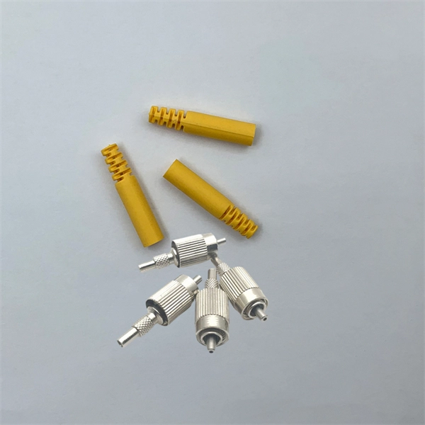
Optical connectors are the physical interface that links an optical device to a fiber optic cable. Fiber optics are used in many applications, including medical imaging, automotive, military, industrial, and commercial (e., telecommunications). Each of these. Many people ask the same question: Can you use a fiber optic cable with an RJ45 port? The short answer is no - RJ45 connectors are designed for electrical Ethernet signals, while fiber optics transmit light pulses through glass or plastic. However, modern networks often combine both technologies. An optical fiber connector is a device used to link optical fibers, facilitating the efficient transmission of light signals. An optical fiber connector enables quicker connection and disconnection than splicing. They come in various types like SC, LC, ST, and MTP, each designed for specific. Proper connection of fiber optic cables is essential to harness these benefits fully, as even minor errors can lead to significant performance issues like signal loss. This article will guide you through the necessary tools, materials, and methods on how to connect fiber optic cables effectively. Most SFP fiber optic modules use LC connectors, while SC connectors are mainly found in legacy networks and MPO/MTP connectors are used for high-density cabling rather than directly on standard SFP modules. FC FO LC connectors for fiber optic.
[PDF]

A novel method for aligning multi-core fibers (MCF) provides a systematic approach for MCF splicing in the lab, in cable factories, and in the field. Splicing fiber optic cable is an extremely important phase for making dependable, high-speed communication infrastructures. Regardless of the type of fiber network you're deploying, be it for telecom, enterprise data centers, or smart city infrastructure, fusion splicing provides the benefits of. This is where fiber optic cable splicing—the process of creating a permanent, high-performance join between two fiber ends—becomes critical. For network managers and technicians, a poor splice can lead to significant signal degradation, network downtime, and costly troubleshooting. At Turn-Key. W. Zheng, "Automated Alignment and Splicing for Multicore Fibers," in Optical Fiber Communication Conference/National Fiber Optic Engineers Conference 2013, OSA Technical Digest (online) (Optica Publishing Group, 2013), paper OM3I. However, realising its potential depends on one critical process, which is achieving ultra-low-loss fusion splices that maintain performance and. This guide reveals the secrets to fusion splicing with little fluff—just proven, straightforward techniques refined from years of work in the field. The guide provides the complete workflow, covering safety precautions, tool selection, fiber preparation, fusion operation, quality control, and.
[PDF]

The basic structure of optical fiber consists of three primary components: the core, the cladding, and the buffer coating. The core is the central part of the optical fiber through which light is transmitted. An optical fiber cable is a complex structure designed to protect fragile glass fibers that transmit digital data using light signals. This advanced cabling solution allows fast, secure data transfer and telecom over long distances. Understanding the components within a fiber optic cable enables. In this blog, we will delve into the fundamental components and structure of optical fiber to gain a better understanding of this revolutionary technology. At its core, optical fiber is a thin, flexible, and transparent fiber made of glass or plastic, which serves as a medium for transmitting light. They consist of three main components and are available in several structures suited to different uses. In this article, discover in detail these components and the various structures of fiber optic cables. The core: made of silica, molten quartz, or plastic, in which optical waves propagate. Dielectric material conducts.
[PDF]

The National Electrical Code (NEC) has established eight levels of fire resistance for fiber optic cables. These levels are based on the time it takes for a cable to burn through or melt. Corning Optical Communications manufactures quality flame retardant optical fiber cables for indoor applications, which comply with the requirements of the National Electric Code® (NEC® 2023) published by the National Fire Protection Agency (NFPA). To ensure compliance to these requirements, a. Understanding the listing requirements of fire alarm circuit cables can help you make sense of the cable alphabet soup. Here are some highlights from Part IV of Article 770. There's plenty of "expansion room" built into Article 770. Part I ends with Section 770. 44. Cabling Installation & Maintenance - Classes 1, 2, 3, and 4, communications, fire alarm, and optical fiber cables are all addressed in the NEC. By Stanley Kaufman, PhD, CableSafe Inc. UL Solutions' long-standing history in certification and Standards development makes us a trusted thought leader in the. Understanding the fire ratings and jacket options for fiber optic cables is crucial for ensuring optimal performance and safety. This technical guide will provide a comprehensive overview of these factors, their implications on cable resilience and transmission, and tips for making informed.
[PDF]
Metal conductors in cables serve to conduct electricity, while optical cables use optical fibers to transmit light signals, and optical fibers are thin, flexible media that transmit light beams, forming the core part of optical cables. Let's take a closer look at. Yes, there can be differences between optical cables in terms of their construction materials, connector types, and the quality of the glass fibers used. These factors can affect the cable's ability to transmit data effectively over long distances and at high speeds. It's important to choose the. Toslink—short for “Toshiba Link”—is a very specific subset of fiber‑optic technology created in 1983 to move consumer‑level digital audio from one box to another. Let's take a closer look at these differences. Cables physically connect these devices, enabling them to communicate within a network. In computer networking, it is very important to know the distinctions between the different. These cables are used mainly for digital audio connections between devices. A fiber-optic cable, also known as an optical-fiber cable, is an assembly similar to an electrical cable but containing one or more optical fibers that are used to carry light. They are mainly used in telecommunications, data transmission and consumer electronics. Compared to traditional cables that carry electrical signals, optical ones have Cables some advantages.
[PDF]

This article will provide an in-depth analysis of outdoor cable types, key selection criteria, core installation steps, critical precautions, as well as subsequent testing and maintenance guidelines, helping you build a robust and durable outdoor optical communication link. Therefore, understanding the characteristics of outdoor fiber optic cables and mastering proper installation methods is crucial. Plan your outdoor fiber installation carefully by surveying the site, choosing the right cable type, and following FOA and OSP standards to ensure reliability. In this video, we'll walk you through the process of establishing a robust outdoor fiber connectivity solution. Follow our guide and establish a r. more Welcome to. Running a cable through an exterior wall can be a daunting task for many homeowners, but with the right tools and techniques, it can be done efficiently and safely. With the increasing demand for high-speed internet and reliable networking, it's essential to know how to properly install CAT 6 cables outdoors. In this article, we'll take you.
[PDF]
This article outlines five specific steps for repair: 1) Identify the break; 2) Cut out the damaged section; 3) Strip the cable; 4) Trim the fiber ends; 5) Test the repair. DIY fiber optic cable repair kits are increasingly popular for those who prefer home repairs. Before diving into repairs, it's essential to grasp the basics of fiber optic cables. These cables consist of a core (glass or plastic) that carries light signals, surrounded by cladding to reflect light inward, a buffer for protection, and an outer jacket for durability. Single-mode fibers (SMF). With the right tools and techniques, you can efficiently repair damaged fiber cables and restore reliable performance. The first step requires that you find the damage. To do this, you can use an OTDR, Optical Time Domain, Reflectometer. This is a testing device that looks at optical signals in the cable which can identify irregularities in the structure. This involves a set of specialized equipment such as a fusion splicer, fiber cleaver, and fiber stripper, among others. When it comes to ensuring nice network experiences for users, the condition of a fiber. A cut or damaged fiber optic cable can disrupt your network, but it is repairable with the right tools and techniques.
[PDF]
Optical fiber consists of a and a layer, selected for due to the difference in the between the two. In practical fibers, the cladding is usually coated with a layer of or. This coating protects the fiber from damage but does not contribute to its properties. Individual coated fibers (or fibers formed into ribbons or bundles) then ha.
[PDF]

What is the main cause of attenuation in fiber? Attenuation in fiber mostly happens from absorption and scattering. The fiber material takes in some light as it moves. Both of these things make the signal weaker as it goes through the. Optical Signal Attenuation is the single greatest factor limiting the distance and performance of your network. Understanding it is crucial for anyone involved in data centers, telecommunications, or enterprise networking. This guide will demystify signal loss, explore its causes, and show you how. Optical fibers are a key component in modern communication systems, carrying signals over long distances. However, even the most advanced optical fiber suffers from attenuation, which is the loss of signal power as it travels along the fiber. Understanding the causes of signal loss and implementing mitigation strategies is essential for maintaining network efficiency. From infrastructure planners to telecom engineers. Optical fiber technology enables rapid data transmission over vast distances by guiding light signals through thin strands of glass. Losses can be introduced by various means such as intrinsic material absorption, scattering, bending, connector loss and more.
[PDF]
In this article, we will explore the six proven ways to fix optical cable issues, enabling you to get back to enjoying high-quality sound and visuals without a hitch. Before delving into troubleshooting, it's useful to understand exactly what an optical cable is and how it works. Optical cables, often referred to as fiber optic cables, have become integral to our everyday lives, delivering high-speed internet and crystal-clear audio and visual signals. However, like any technology, issues may arise, leading to anxiety and frustration when your optical cable isn't. Whatever the case, In this article, we have discussed the fixes that you can apply when your optical cable is not working. Since a damaged optical cable will prevent you from using your external speakers, you need to solve it as soon as possible. These cables are made entirely of dielectric materials, such as. Optical cables have revolutionized how we transmit audio and visual signals, providing a crisp connection with minimal interference. They use light to carry data, making them an excellent option for connecting devices like televisions, sound systems, Blu-ray players, and gaming consoles. However. While a cut or damaged fiber optic cable can temporarily take your network down, it is possible to quickly fix the cable with the right tools. This wikiHow article will teach you how to splice a cut fiber optic cable back together with a fiber optic stripper and cutter and a fiber optic crimper.
[PDF]

The operation and skills of fiber optic fusion splicing technology can be mainly divided into five steps: fiber stripping, fiber cutting, fiber melting, fiber sleeve, and fiber winding. Two types of splices are used in fiber optic cabling one is Mechanical the other is Fusion. And tools used for fiber fusion: fusion splicer; fiber cleaver; cable stripper; fiber optic stripper; alcohol;. These specialized devices are engineered to manipulate, terminate, join, and verify light-carrying strands without introducing microscopic fractures or contamination. At Weunion, we categorize these essential instruments into four primary operational phases: Preparation: Removing protective layers. Various techniques can remove the coating: Regardless of the method used to strip the coating, it is important to use the correct tools and techniques to prevent damage to the bare glass. Ensuring the fiber. What is Fiber Optic Splicing and Why is it Needed? – #1. Use and Maintain Your Cleaver Correctly – #3. Set Your Fusion Parameters in a Systematic Way What is Fiber Optic Splicing and Why is it Needed? First, let us understand the meaning of the term. Fusion splicing joins two optical fibres end-to-end using heat, creating a seamless connection for minimal signal loss. owever, proper cable preparation is essential before firing up your fusion splicer. A poorly prepared fibre can lead to weak splices, high attenuation, or complete failure.
[PDF]
Typical rates range from $0. 00 per ft depending on terrain, access, and required precision for termination. Basic — 1,000 ft single-mode run indoors with minimal termination: Cable $0. 00/ft, Permits $150, Accessories $100. Total ≈ $2,650–$3,100. EU - Optical Fiber Cables and Bundles - Market Analysis, Forecast, Size, Trends and Insights. Update: COVID-19 Impact This report provides an in-depth analysis of the optical fiber. CRU provides comprehensive, accurate and up-to-date price assessments and research reports for bare optical fibre across various key regional markets, combined with insights into the factors and events affecting markets. The total consumption indicated a noticeable increase from 2012 to 2025: its value increased at an average annual rate of X% over the last twelve-year period. The trend pattern. Buyers typically pay for fiber optic cable by length, fiber type, and installation complexity. Main cost drivers include cable grade (indoor vs outdoor, armoured), distance, and labor for trenching, splicing, and termination. Commercial building installations with 100-200 network drops generally range from $15,000 to $30,000. Single-mode fiber costs less per foot than multimode fiber, but it requires more. The unit cost of fiber optic cables can vary from $0. Here's a general pricing reference: Cable TypePrice Range (USD/meter)Simplex / Duplex Indoor Cable$0. 50Multimode (OM1/OM2/OM3)$0.
[PDF]