In an Ethernet patch panel diagram, each port on the patch panel is represented by a numbered or labeled square or circle. The diagram typically includes details such as the port numbers, cable types, and the devices connected to each port. Ethernet patch panel diagram is a visual representation of the connections between Ethernet cables and network devices, such as switches and routers. It provides a clear overview of how the network is structured, allowing network administrators to easily troubleshoot and manage the network. This information can be used to track the location of devices, their serial numbers, and their IP addresses. Change Management: Patch panel connection diagrams can be used to track. A patch panel is an essential component in a network system that provides a central location for connecting multiple devices or cables. The patch panel serves as. A pair of managed Gigabit Ethernet rack-mount switches, connected to the Ethernet ports on a few Panduit patch panels using Category 6 patch cables. (All equipment is installed in a standard 19-inch rack. Each port has a patch connection that links it to another port in another part of your building.
[PDF]
While both core and normal switches play crucial roles in maintaining efficient data flow, their functionality and applications vary significantly. This guide unpacks the core differences, helping you understand which type suits your networking needs. What Are Core and Normal. Core Layer: The core layer is the backbone of the hierarchy network. The primary transmission and routing of data signals take place at the core layer only. It consists of network switches that perform routing and switching of the data. The devices like high-capacity transmitters are placed in this. What are the Differences Between the Core Switch and Normal Switch? A core switch is not a type of switch, but a switch placed at the core layer (the backbone of the network). It provides a high-speed connection between different distribution layer devices. Edge = connects the internal network to the external WAN/Internet. Access vs Distribution: Access = user/device connectivity. Distribution = aggregates access, applies policies, routes traffic. Distribution vs Core: Distribution = policy. Data center-grade switches are characterized by high-quality business assurance and control recognition capabilities. They feature end-to-end flow control and backpressure mechanisms, ensuring stable and reliable data transmission, and smoothing out network surges. They offer higher reliability and.
[PDF]
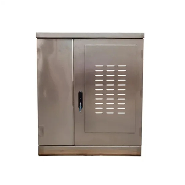
Main distribution boards (MDB) manage and distribute electrical power from one or more sources to branch circuits in an LV distribution system. It provides circuit breakers for each branch circuit to prevent faults and incidents. Panelboards are designed to meet UL 67 and NEMA Standard PB1. What is the difference between a switchboard and a panelboard? Switchboards and panelboards provide a similar functionality in a power distribution system. Panelboards are typically flush mounted or surface mounted and are limited to a. A distribution board (also known as panelboard, circuit breaker panel, breaker panel, circuit breaker, electric panel, fuse box or DB box) is a component of an electricity supply system that divides an electrical power feed into subsidiary circuits while providing a protective fuse or circuit. According to NEC Article 100, branch circuits are the conductors between the final overcurrent device protecting the circuit and the outlet. This article deals with lighting and appliance branch circuits. The article also covers motors or. A panelboard is a distribution assembly designed to divide an incoming electrical feed into numerous smaller branch circuits. Each circuit is protected by its own circuit breaker. Inside a distribution box are components. multiwire). Branch device and terminates at another circuits are usually low current (30 amps or distribution center, panelboard, or load less), but can also supply high curre ts.
[PDF]

Cable Trays* — Max two 24 in. (610 mm) wide by max 6 in. (151 mm) deep open-ladder cable tray with channel-shaped side rails formed of 0. 54 mm) thick aluminum or min 0. In practice, cable tray dimensions are a system of interrelated measurements —width, depth, length, and material thickness—that directly affect cable fill compliance, heat dissipation, structural loading, and long-term expandability. From an engineering standpoint, cable tray dimensions are not. Perforated Cable Tray System expertly constructed from high-grade stainless steel, offering exceptional durability and resistance to corrosion. With side height 100mm. A properly designed and installed cable tray system will provide. Studs — Wall framing to consist of wood studs or channel shaped steel studs. Wood studs to consist of nom 2 by 4 in. Additional studs shall be used to completely frame. Best Size: Here, deep trays (75mm to 150mm) are used since power cables are typically thick and heavy. Data cables, such as your Wi-Fi or computer ones, are extremely sensitive. They do not get hot; however, they do not like to hang or sag. In case a data cable folds in an excessive manner, the. ect the minimum bend ra-dius for cables as they exit the bottom of the cable tray. A rung spacing of 6 to 9 inches (150 to 230 mm) is preferable when the cable tray cont d for instrumentation and control applications that require additional protec eferred to support and protect numerous small.
[PDF]

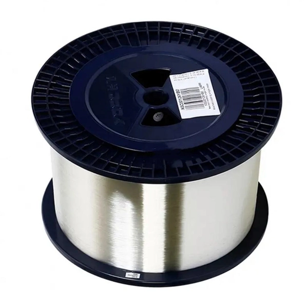
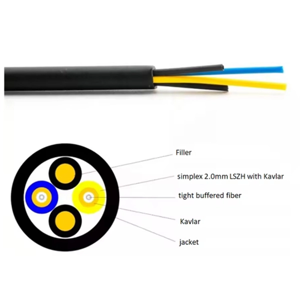
An Optical Splitter, also known as a beam splitter, is a passive optical device that divides a single input optical signal into two or more output signals. Conversely, it can also combine multiple signals into one. Knowing the difference between a splitter and an optical coupler helps you build better networks. You make your network work better when you pick the right device for each job. You can connect many users to one port with 1:n or 2:n splitters. By dividing a single optical signal from a central Optical Line Terminal (OLT) into multiple outputs for Optical Network Terminals (ONTs) at users' homes, splitters eliminate the need for dedicated fibers to each residence—slashing infrastructure costs while scaling network reach. This guide. In a Passive Optical Network (PON), a single optical fiber carries massive amounts of data using light. Signal Input: The fiber splitter receives the optical signal from the upstream network node and enters the splitter through the input fiber. Signal Distribution: Inside the splitter, according to the design structure and different. Splitters are passive optical devices that divide or combine optical signals, and they come in various types, including power splitters, uneven splitters, and wavelength-division multiplexing (WDM) splitters. Each type serves specific applications, enabling efficient use of optical infrastructure.
[PDF]

A ladder type cable tray tee is a fitting used to create a branch in a cable tray system, allowing cables to be routed in three directions. Its "T" shape provides a secure and efficient way to split cables from a main tray into two separate paths, ensuring organized and flexible. A cable tray tee and tee cover are components used in cable management systems to support and protect electrical and data cables. Here's a brief explanation of each:. Rigid steel cable tray tee fitting with zero tangent, safety bottom, and full accessory support. ventilation to heat producing cable such as power communication and other with the same or different width of the cable run. All fittings are available in sizes and types corresponding to the straight cable tray sections. These fitting are including: elbow, horizontal cross, vertical inside. NOTE : Equal or un equal tees can be supplied. When ordering state widths W1xW2xW3.. Office: 147/22 Nguyen Sy Sach Street, 15 Ward, Tân Binh Dist, HCMC,VN. Is it possible to connect 2 cabletrays with a "branch piece (left picture)" instead of a "tee (right picture)". The tee has 3 connectors, the branch piece only has 1 connector. I would like to ajust the "Type properties -> Fittings -> Tee" with the branch family, but can't get it accomplished.
[PDF]

This guide provides essential information for B2B buyers navigating the US-Russia trade restrictions, including duty rates, prohibited products and compliance requirements that affect sourcing decisions. Let's take a look at different factors that could affect 100G QSFP28 optical module cost. While optical transceiver development has gotten simpler over the years, it does involve full engineering development to design, validate, and qualify. Generally, the two main milestones in this phase are. View Trade Statistics by Country including trade summary, exports and imports by partner and products along with tariff and development indicator. Search by product name or upload HTS codes to see real-time duty calculations. This tool does. On February 11, 2026, the US modified Column 2 tariff rates on Russian-origin goods in response to what the government termed "threats to the United States by the Government of the Russian Federation. " This action, coupled with OFAC sanctions updates, represents a tightening of economic pressure. The QSFP28 optical transceiver module is designed for use in 100GBASE Ethernet throughput up to 100km over single mode fiber (SMF) using a wavelength of 1310nm via duplex LC connectors. The current US sanctions on Russia operate through multiple federal agencies, creating a.
[PDF]

Interested in joining the Wizards Play Network? There are a few things you should know first. Ready to Join WPN? To start, you will need to sign in with your individual Wizards Account, or create one if you don't have one. Ready to learn more about owning an Club Z! in-home care franchise? Request franchise information below. At Club Z!, we're committed to helping you thrive from day one. You'll receive hands-on training directly from top-performing franchise owners in our network, equipping you with the knowledge. This project is not affiliated with Electronic Arts or the Need for Speed™ brand in any way, shape or form. Need for Speed is a trademark of Electronic Arts. The Horizon of Need for Speed: World is waiting for you. NightRiderz is an open-source project which has started in May 2018, our main goal is to restore the game in its original state, with more features and cars. We are affiliated with Soapbox Race World, a team of developers that has basically. Club Z! is one of the largest and fastest-growing tutoring franchises in the U., with 450+ locations and a track record of proven results, innovation, and strong franchisee support. Its consultant members are the most senior, qualified consultants in the industry – all of whom have owned their own business and can speak from both experience and the heart. Wizards Accounts are only for individuals, so please do not create an.
[PDF]
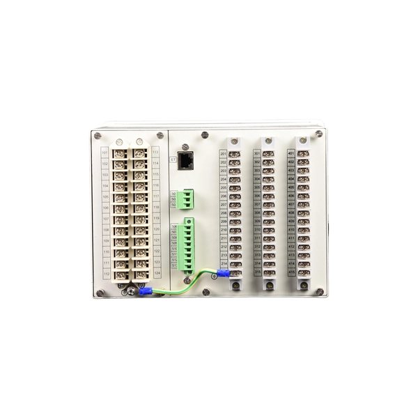
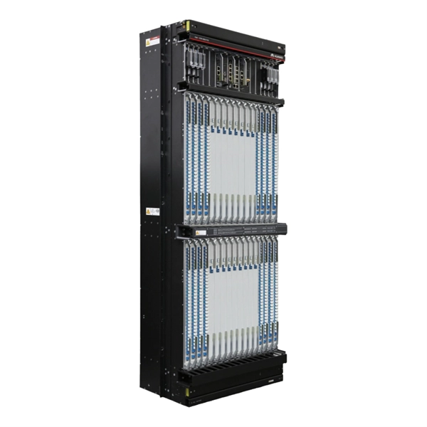
Huawei MA5683T is an aggregation Optical Line Terminal (OLT), it supports up to 6 service slots and can support a maximum of 12,000 subscribers (GPON). MA5683T has GICF/X2CS Uplink Board available for selection, and two power slot redundancy for DC power input. Ethernet link aggregation increases link bandwidth by bundling multiple physical links to form a logical link. Link aggregation can work in manual mode or Link Aggregation Control Protocol (LACP) mode. In manual mode, you must manually create an Eth-Trunk and add member interfaces to the Eth-Trunk. As shown in Figure 1, SwitchA and SwitchB are connected to the networks of VLAN10 and VLAN20, respectively, via Ethernet links, and there is a large amount of data traffic between SwitchA and SwitchB. Link aggregation has the following advantages:. Original operating mode: Two S5700s were configured with Eth-Trunk1, and the ports of the three lines that need to be communicated were added to Eth-Trunk1. Set the port to access to allow the corresponding VLAN to pass; so that the two floors of the network can communicate normally In this way. And there are two link aggregation types. In LACP mode, there are active and backup links and backup links are used for redundancy. For this example, we. Link Aggregation is a technology defined in IEEE 802. It enhances bandwidth, provides fault tolerance, and allows load balancing between connected devices. Key benefits of link aggregation: Higher.
[PDF]
For systems with fewer than 32 channels, a core switch is generally unnecessary. Basically, the core switch is not required under 50 channels, the second layer switch plus router can be used, and the 100-channel or so will use the efficient routing function of the core switch. First of all, the 100-channel monitoring belongs to a medium-sized network. His network is under. Many engineers also say that I can manage 300 cameras without a core switch, and that's fine! With 10 years of experience as a security R&D engineer, I will tell you how to configure a core switch for cameras. What is a core switch? A network has three layers: access, aggregation, and core. Generally, large enterprise networks and Internet cafes need to buy core switches to achieve robust network scalability to protect the original resources. We will use. Core switches and edge switches are two essential components that play distinct roles in the functioning of a network.
[PDF]
Housing Integrity: Cracked, melted, or physically broken outer casings. Electrical Failure: Severe internal burn marks or "fried" traces that prevent a safe rebuild. Completeness: Units that have been scavenged for internal parts or are missing proprietary hardware. This document describes how to identify, isolate, and troubleshoot symptoms of hardware failures on Catalyst 9600 Supervisors and Line Cards. There are no specific requirements for this document. The information in this. If the switch has rebooted unexpectedly, you can follow the steps to troubleshoot the hardware. If your core looks different. This topic covers the steps for troubleshooting bootup, crash, network, software, and audio issues related to the Q-SYS Core 110f processor and Cinema Core 110c processor. It details what information to collect post-event to help identify the root cause. Requirements and Components Used Requirements: None specific to hardware/software versions. Lab. Hardware faults on CE switches include power supply faults, fan faults, card power-on failures, unexpected card restarts, abnormal optical module status, and abnormal interface status. The following information helps you quickly locate hardware faults. Common Causes of Power Supply Faults Common.
[PDF]

Use two fibers: one dedicated to TX, the other to RX. Both sides transmit and receive at the same wavelength (common values: 850 nm MM, 1310 nm/1550 nm SM). The front panel is usually labeled TX and RX, and you cross-connect TX→RX, RX→TX with a duplex patch cord. Switch optical port intercommunication means that the optical fiber ports of two switches are connected to each other to achieve the purpose of network connection. The connection between two or more Ethernet switches in a certain way (Uplink port, etc. ) is called the cascade. SFP modules insert into these slots and and require two strands of fiber, typically duplex Using multi mode fiber (for runs under 1000 feet) or duplex single mode fiber (for runs over 1000 feet). This is a cost-effective and high performance way to connect network switches. Use one fiber strand for both. The switch supports 10 Mbps, 100 Mbps, and 1000 Mbps connections. Using Gigabit Ethernet (1000 Mbps), the switch sends files across the network at speeds up of to 2000 Mbps due to the full-duplex nature of Gigabit Ethernet connections. You can either connect 24 Ethernet copper cables or 22 copper. Port types are limited to two: optical and Ethernet. Optical ports on switches typically accommodate optical modules for transmitting data via fiber optic cables. In situations where there's a shortage of Ethernet ports, some users may insert Ethernet port modules into optical ports to connect with.
[PDF]
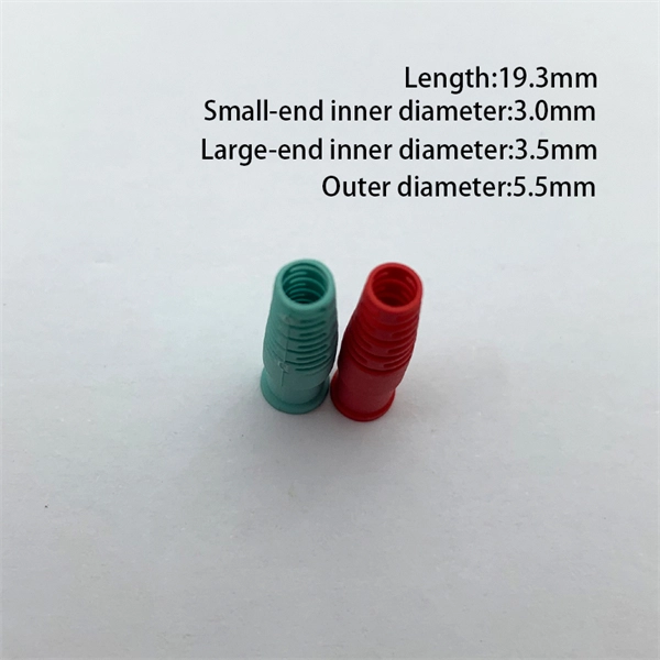
Step 3 Remove the cables or optical modules from the old card. Press the two green locking clips in the middle of the card to eject the ejector levers. Turn the ejector levers outward and slowly pull the card out. Place the replaced. Unplug the optical fibers from the optical module before removing it. Install or remove optical fibers carefully to avoid damaging the fiber connectors. If an optical module cannot be completely inserted into an optical. Page 7 Optical port USB storage device Wi-Fi terminal 1. Wear an ESD wrist strap or ESD gloves when replacing the optical module. Therefore, replace an optical module only when you confirm.
[PDF]
The proposed study will be based on three components, namely: (A) support to the establishment and operationalisation of the Digital Development Agency (DNA); (B) the elaboration of a Master Plan for the development of broadband infrastructures, a decision support tool for the. The proposed study will be based on three components, namely: (A) support to the establishment and operationalisation of the Digital Development Agency (DNA); (B) the elaboration of a Master Plan for the development of broadband infrastructures, a decision support tool for the. This intervention concerns the support to the setting up and operationalisation of the National Digital Agency (ADN), the elaboration of a Master Plan for the development of broadband infrastructures and the complete feasibility studies of the Central African Fiber Optic Corridor, DRC component. OTTs and telcos, such as Facebook or Orange, supported by funders and African governments, have joined forces to accelerate the deployment of high-speed connectivity infrastructures. The Congolese Minister of Telecoms, Augustin Maliba, signed the related memorandum of understanding (MoU) on April 7, 2025. "With the support of the. Learn about the market conditions, opportunities, regulations, and business conditions in congo, the democratic republic of the, prepared by at U. Embassies worldwide by Commerce Department, State Department and other U. agencies' professionals Democratic Republic of the Congo -.
[PDF]

This diagram shows how the RJ45 cable is connected to the PoE switch, allowing it to power devices such as IP phones and cameras. In this article, we will explore the wiring diagram for a PoE switch, which provides a visual representation of how the switch connects to various devices. Each device is represented by a. Do you want to set up a new computer network in your home or office? Chances are, you'll need a Poe switch wiring diagram. Not only do these diagrams provide all the information you need to install a network, but they also help make the process easier and more efficient. For those who don't know. A PoE Switch, also known as Power over Ethernet Switch, is a network device that allows users to power and connect devices such as IP cameras, VoIP phones, and wireless access points. In essence, a PoE Switch can be described as regular switch with added ability of Power over Ethernet which allows. PoE technology enables the transmission of both data and power over a single ethernet cable, simplifying network setups and eliminating the need for additional power sources. This is particularly useful in scenarios where devices like IP cameras, wireless access points, or VoIP phones need to be. Here, you can see the details, Keep the copper strips towards your face and count the pin number or pin position from left to right. The T568B also has a total of eight pins and sight different colors.
[PDF]