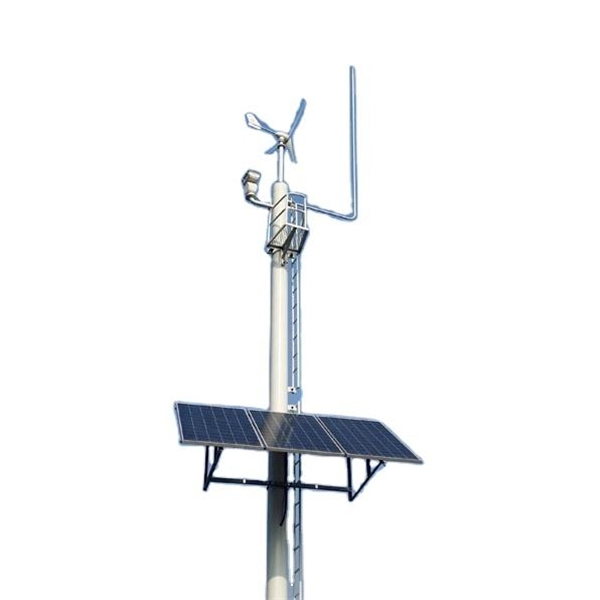
This whitepaper describes the various communications technologies while describing the inherent limitations and advantages. Off-grid communication systems, powered by sustainable energy sources like solar, enable vital connectivity in remote locations, during emergencies, and for operations requiring autonomous communication capabilities. From remote European mountain refuges to industrial facilities operating in. Introduction: Free Space Optics (FSO) is a wireless optical technology that transmits data via laser beams. It leverages light waves to transmit and receive data in a Line-of-Sight (LOS) path between buildings. Unlike Optical Fiber Cable (OFC), FSO uses air as the medium for data transportation. Solar powered communication systems, harnessing the sun's energy to power various communication devices and networks, represent a significant step towards achieving this goal. This essay will explore the diverse applications, benefits, challenges, and future prospects of these systems. This paper aims to explore the FSO system, analyze previous research, and discuss the challenges associated. Solar light communication is a technology that utilizes light emitted from solar-powered sources to transmit information. Employs modulation techniques to encode data within light signals, 3. Low Noise Amplifiers (LNAs) are a key component in many electronic systems and communication devices. These critical elements are used extensively to amplify.
[PDF]
Although fiber optic networks present many advantages, there are also some disadvantages to take into consideration. These include physical damage, cost considerations, structure, and the possibility of a “fiber fuse”. By the early 1990's, as the internet was becoming popular in the public realm, fiber optic cabling started to be laid around the world. There was a big push to wire the world in order to. Optical fiber is a type of medium used for data communication or data transmission with the help of light pulses. Optical fiber is a hair-thin flexible stand made up of glass. It is capable of transmitting optical signals from one point to another over long distances. These days, optical fibers are. Fiber optic transmission has become the cornerstone of high-capacity communication networks, powering residential broadband, hyperscale data centers, 5G, IoT ecosystems, and global long-haul infrastructure. Additionally, fiber optic cables are delicate and require careful handling and installation. Electromagnetic interference (EMI) is a disturbance caused by electromagnetic radiation from an. There are many advantages of using these cables over other kinds of communication cables, like the bandwidth of these cables is high, and they are less vulnerable than metal cables.
[PDF]
Despite its numerous advantages, the use of InP in high-speed optical devices does come with challenges. The production process for InP can be complex and costly, which may limit its widespread adoption. Here are some key properties of Indium Phosphide (InP): Here are the key advantages of using Indium Phosphide: Superior Electron Velocity: InP boasts a much higher electron velocity compared to silicon (Si) and gallium arsenide (GaAs), approximately 5 times greater. Direct Band Gap: This property. Indium phosphide is a photonic integrated circuit (PIC) material suited for active functionalities. Beyond passive light routing, it can generate, amplify and detect light. Read on this page to learn more about indium phosphide characteristics, applications, and its comparison to other PIC. Indium Phosphide (InP), a duo-semiconductor born from the union of indium and phosphorus, has been thrust into prominence within the optoelectronics arena. Indium phosphide (InP) diodes are emerging as a promising semiconductor material for optoelectronics applications due to their. Abstract—A summary of photonic integrated circuit (PIC) platforms is provided with emphasis on indium phosphide (InP). Examples of InP PICs were fabricated and characterized for free space laser communications, Lidar, and microwave photonics. A novel high-performance hybrid integration technique.
[PDF]
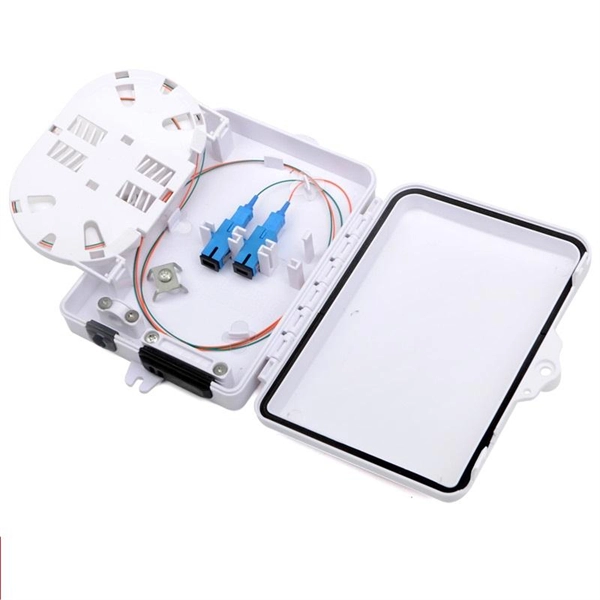
Advantages: Lightweight and easy to install. Excellent corrosion resistance and electrical insulation. Versatile design options to meet various requirements. Terminal boxes are essential components used for connecting electrical circuits, and the choice of materials significantly impacts the product's overall performance, safety, and lifespan. Below is a detailed analysis of commonly used materials for terminal boxes, along with their advantages and. ve Neutral Point Clamped). The reader will gain insight into elementary thoughts of how these 3L devices work, where advant ges and disadvantages are. Some hints concerning the layout/setup of 3L modules are given as well. However, the information given is not exhaustive and the responsibility for. Explore LCC technology—a key driver for the miniaturization and performance enhancement of modern electronic devices. Learn which is better for your electrical projects based on durability, safety, and cost. It's easy to overlook the small details when working on electrical projects. In many cases, there are several correct options, each with advantages, disadvantages, and costs to consider. Regardless of which box you select, a key factor. The fiber terminal box facilitates easy fixing, splicing, and mechanical protection of the fiber optic cables. With its user-friendly design and removable components, it simplifies troubleshooting tasks and reduces operational costs.
[PDF]
This article will deeply explore the unique charm of optical circulators from five aspects: the forefront of technological innovation, efficient cyclic transmission, wide application fields, excellent and stable performance, and future development prospects. Frontier of. An Optical Circulator is a non-reciprocal device that routes light from one port to the next, in a unidirectional manner. This unique device has broad applications in many fields, from optical telecommunications to fiber-optic sensor systems. They are crucial components in modern optics and photonics, enabling the efficient routing of optical signals. The basic principle of an optical. The evolution of optical circulators can be traced back to the advancements in fiber optics technology during the late 20th century, which necessitated the development of devices capable of managing complex light pathways. They are technically related to Faraday isolators, and on a broader scale similar to electronic circulators.
[PDF]

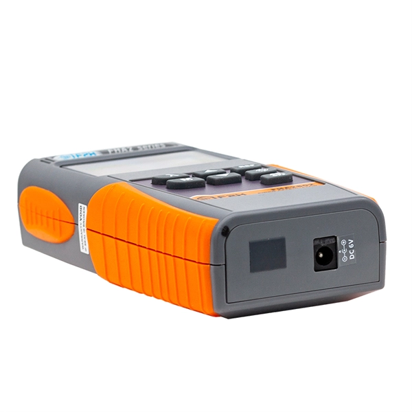
In this case use an optical power meter (OPM) and test the input port of the splitter for the optical power level (dBm) from the OLT at 1490 nm. If there is no or reduced power then the patchcord or OLT is the culprit. If the power level is reduced it could be as simple as a. So for this simple 1X2 splitter, how do we test it? Simply follow the same directions for a double-ended loss test. Attach a launch reference cable to the test source of the proper wavelength (some splitters are wavelength dependent), calibrate the output of the launch cable with the meter to set. Optical splitters in the outside plant (OSP) are used mostly in passive optical networks (PONs) for fiber-to-the-user (FTTx) networks, and are often overlooked as failure points. In this article I focus on a few basics of optical splitters, their applications, typical causes of failures, and how to. Now, we test the simplest 1x2 optical splitter as the picture shown below. 001 dB), OTDR (for reflection event detection). Cleaning tools. The CertiFiber® Pro Optical Loss Test Set (OLTS) can be used to check that the loss of a PON Splitter (often referred to in various standards as a non-wavelength-selective or wavelength-selective branching device) to check that it is within the allowed defined limits. The CertiFiber® Pro has an.
[PDF]
A passive optical network (PON) is a fiber-optic telecommunications network that uses only unpowered devices to carry signals, as opposed to electronic equipment. In practice, PONs are typically used for the last mile between Internet service providers (ISP) and their customers. In this use, a PON has a point-to-multipoint topology in which an ISP uses a single device to serve many end-us. Components and characteristicsA passive optical network consists of an (OLT) at the service provider's central office (hub), passive (non-power-consuming) optical splitters, and a number of (ONUs) or. Passive optical networks were first proposed by in 1987. Two major standard groups, the (IEEE) and the. A PON takes advantage of (WDM), using one wavelength for downstream traffic and another for upstream traffic on a (ITU-T, typically OS2). BPON, EP.
[PDF]
Wall-mounted fiber distribution frames are typically designed as box-like structures, ideal for locations with fewer cables and fiber cores. Whether you're building a central office, data center, or FTTx distribution network, understanding the right ODF. FDF, or Fiber Distribution Frame, is a key component used for the termination, utilization, and management of optical cables between wiring rooms and equipment rooms. In structured cabling systems, ODFs are suitable for horizontal cabling between equipment or their terminations, as well as. A distribution boxes is an essential device that manages the safe and efficient flow of electrical power throughout different areas of a building or facility. It is commonly used in homes, offices, and industrial settings to control and protect electrical circuits. Understand its role in electrical systems and safety.
[PDF]

At its core, a fiber termination box combines hardware and software components to facilitate fiber optic connections. The hardware includes protective enclosures, splice trays, adapters, connectors, and patch panels. A Fiber Terminal Box (FTB) is a customer-side termination and distribution device used at the end of the optical network. It is small, so it is considered a mini version of the optical distribution frame or optical distribution frame (ODF). The number of ports of fiber optic junction boxes ranges from 8. A fiber optic junction box, also known as a fiber optic distribution box or termination box, is a protective enclosure that facilitates the connection and management of fiber optic cables. It serves as a central point for organizing and distributing optical fibers, ensuring efficient connectivity. Fiber termination boxes are essential components in modern telecommunications infrastructure. They serve as the critical junction points where fiber optic cables connect, splice, and distribute data signals efficiently and securely. Here's a structured breakdown. This article provides an in-depth comparison of fiber terminal boxes and junction boxes to help clarify their differences and deepen your understanding.
[PDF]

A typical fiber optic splice enclosure consists of several key components that work together to protect and organize the fiber splices. Standard enclosures contain: 1) Housing, 2) Cable fixation clamps, 3) Splice trays, 4) Sealing system. A splice box (also known as splice distributor) is a housing in which fiber optic cables begin or end. Fiber optics are fanned out in splice boxes that are situated at the end of fiber optic transmission paths. Optical cable joint box The optical cable joint box permanently connects two optical cables together and has a joint part for protecting components. The optical cable connection part, that is, the optical cable joint, is the part where the. An optical cable split fiber box, also known as a fiber distribution box or fiber optic splice closure, is a device used to terminate, splice, and distribute optical fibers. In this response, we will focus on the. This guide optimizes the original text by delving deeper into the three pillars of fiber network longevity: the impact of splicing technology, the strategic selection of splice boxes, and the essential maintenance protocols needed to ensure sustained, high-speed functionality. Fibre optic cables are manufactured in standardized lengths –.
[PDF]

It connects to two independent power sources, enabling automatic switching to a secondary source during primary source failures. This seamless transition prevents disruptions to connected devices and enhances operational reliability. A dual power switching box is precisely the kind of gadget that guarantees a constant flow of electricity as it enables the user to shift the operational state between two different energy supplies. It can be found in homes, workplaces, factories, and anywhere else where sudden cuts of energy can. The ATS Dual Power Distribution Box plays a pivotal role in providing efficient low-voltage power solutions, ensuring that power flows seamlessly, even in the event of an outage. This comprehensive guide offers insights into the mechanisms and benefits of the ATS Dual Power Distribution Box. Transfer switches and sub panel boxes are key components in dual power switching cabinets. Transfer switches automatically switch between power sources during outages, ensuring uninterrupted power and system reliability. This redundancy ensures that if one power source fails, the other can immediately take over, minimizing downtime and preventing. A dual power switch helps you manage two power sources for one system. You can use it to keep your equipment working if the main power stops. This device quickly changes from the main supply to a backup source. This seamless transition.
[PDF]

Multi-mode fiber optic patch cords utilize a larger core size, typically around 50-100 microns, allowing them to carry multiple modes of light. This design enables the transmission of data over relatively short distances with high bandwidth capabilities. A fiber-optic patch cord is a fiber-optic cable capped at each end with connectors that allow it to be rapidly and conveniently connected to telecommunication equipment. This is known as interconnect-style cabling. A fiber-optic patch cord is constructed from a core with a high refractive. These short fiber optic cords connect transceivers, switches, patch panels, and servers. Without them, even the best optical modules and switches cannot deliver performance. As data rates increase from 10G → 100G → 400G → 800G, patch cables must handle more bandwidth, more density, and stricter. Fiber optic patch cords, also known as fiber optic patch cables or fiber jumpers, are indispensable components in modern optical networks. They act as the critical link for interconnecting devices like optical switches, servers, and distribution frames. Understanding the various technical. Fiber patch cables, also called fiber-optic patch cords, are cables typically containing one or two optical fibers, which are equipped with standardized fiber connectors on both ends. The function of the fiber patch cord.
[PDF]
6Wresearch actively monitors the Papua New Guinea Vertical Cavity Surface Emitting Laser (VCSELs) Market and publishes its comprehensive annual report, highlighting emerging trends, growth drivers, revenue analysis, and forecast outlook. How does 6W market outlook report help businesses in making decisions? 6W monitors the market across 60+ countries Globally, publishing an annual market outlook report that analyses trends, key drivers, Size, Volume, Revenue, opportunities, and market segments. This report offers comprehensive. Use this vertical cavity surface-emitting lasers buying guide to compare major types, define selection criteria, and find suppliers: Professional purchasing of high-value photonics products is a substantial responsibility, where a structured decision-making process is essential. 5 Mm²), End-User Industry (Telecom, Mobile and Consumer, Automotive, Medical, Industrial, Aerospace and. The global market for Vertical Cavity Surface Emitting Laser (VCSEL) was valued at US$2. 6 Billion in 2024 and is projected to reach US$7. 2% from 2024 to 2030. A vertical-cavity surface-emitting laser (VCSEL) is a type of semiconductor laser diode that emits light vertically from the surface of a semiconductor wafer.
[PDF]
This buying guide helps network engineers and field teams choose the right optical solutions for edge computing sites, from SFP and QSFP pluggables to DWDM and PON transport. High-Power Marking/Engraving Systems: These are industrial tools (20W-200W) for permanent part marking and material processing. This specialization requires buyers to. Use this laser pointers buying guide to compare major types, define selection criteria, and find suppliers: Professional purchasing of high-value photonics products is a substantial responsibility, where a structured decision-making process is essential. RP Photonics offers a lot of help: Get. Edge computing deployments fail for optical reasons more often than teams expect: mismatched transceiver optics, budgeted loss errors, or connector/DOM incompatibilities in harsh cabinets. Laser Pointers from the leading manufacturers are listed below. Use the filters to narrow down on the lasers by wavelength, power and various other parameters. View product details, download datasheets and get quotations on products. Laser pointers are a handy aid for presenters who want to highlight aspects of their visual presentations for viewing audiences. Have any questions? Talk with us directly using LiveChat.
[PDF]

Fiber Optic Bundle Pigtails comprises a set of 12 optical pigtails. For ease of identification, these pigtails will come in 12 different colours and are used to be optically spliced with the optical fibers from the optical cable to enable network connection. Fiber optic pigtails are available in various types: Grouped by pigtail connector type, there are LC fiber optic pigtails, SC fiber pigtails and ST fiber pigtails, etc. And by fiber count, 6 fibers, 12. Fiber Optic Pigtails, also known as pigtailed fibers, consist of an optical fiber connector and a section of optical cable. Characterized by having an optical fiber connector on one end and a bare fiber end on the other, they are primarily used to connect optical transceivers or other optical. They are the bridge between fiber optic cables in the field and the equipment or patch panels that manage them. By combining factory-installed connectors with spliced bare fiber, pigtails ensure that network installers can create fast, reliable, and cost-effective terminations. Without pigtails. Executive Summary: A fiber optic pigtail is one of the most commonly specified yet least understood components in structured cabling. Fiber Optic Bundle Pigtails are. Traditional Fusion Splice-On Connectors with pigtails provide factory-polished performance with field-termination convenience within harsh environments. Mass fusion splicing can fuse up to all 12 fibers in one ribbon at once.
[PDF]