Microprocessor-based solid-state digital protection relays now emulate the original devices, as well as providing types of protection and supervision impractical with electromechanical relays.OverviewIn, a protective relay is a device designed to trip a when a is detected. The first protective relays were electromagnetic devices, relying on coils operating on moving par. Electromechanical protective relays operate by either, or. Unlike switching type electromechanical with fixed and usually ill-defined operating voltage thresholds. Electromechanical relays can be classified into several different types as follows: "Armature"-type relays have a pivoted lever supported on a hinge or knife-edge pivot, which carries a moving contact. These relays may.
[PDF]

This guide provides clear cost ranges in USD and practical pricing details for U. Typical cost range for a single relay is $2–$150 depending on type and rating. Buyers typically pay a range for relays, and cost is driven by relay type, coil voltage, contact rating, and packaging. This guide presents practical price estimates in USD, with low–average–high ranges and real-world factors that affect total cost. Assumptions: region, specs, labor hours. Relays. The SEL-351 Protection System has built-in Ethernet and IEEE C37. 118 synchrophasors, and is ideal for directional overcurrent applications. Optional Mirrored Bits communications and power quality monitoring add flexibility to solutions. The SEL-351 is the protection standard for utility and. Buyers typically pay a modest amount for small signal relays and higher sums for industrial or specialty units. The main cost drivers are the relay category (signal, automotive, or industrial), quantity, and installation requirements. Although failure of a protective relay system may have severe local or regional impacts, most protective relay systems are not required to operate to prove they are in working order. Ensuring that. What are Protection Relays and How Do They Work? Protection relays are specialized devices designed to detect abnormal conditions in electrical systems and initiate appropriate actions to protect equipment and personnel. These intelligent sentinels continuously monitor electrical parameters and.
[PDF]

This handbook covers the code of practice in protection circuitry including standard lead and device numbers, mode of connections at terminal strips, colour codes in multicore cables, dos and donts in execution. Also principles of various protective relays and schemes including special protection. Read this document and the documents listed in the additional resources section about installation, configuration, and operation of this equipment before you install, configure, operate, or maintain this product. Users are required to familiarize themselves with installation and wiring instructions. presentation of protection and control relaying. The report will identify methodology behind these practices, present issues raised by the integration of microprocessor relays and the internal logic and external communication configurations, ying. The objective of this presentation is to convey a basic understanding of protective relays to an audience of engineers already familiar with low voltage protective device coordination. HT panel protection relay. The HT power supply is received from GO switch and distributed to the. The handbook for protection engineers includes guidelines on protective circuitry, protective relay principles, and testing procedures for switchgear and relays. It covers standard codes, wiring practices, and norms for protecting generators, transformers, and lines, and provides detailed.
[PDF]
Thermal relays are the perfect solution for providing protection to motors which provides the most precise tripping for the electric motor during single phasing and overload. This article discusses an overview.
[PDF]
The original unstructured record data for the defect of the relay protection devices (RPDs) may contain problems influencing the data mining, and it is lack of quantitative evaluation. So the purpose of this.
[PDF]
Important transmission lines and generators have cubicles dedicated to protection, with many individual electromechanical devices, or one or two microprocessor relays.OverviewIn, a protective relay is a device designed to trip a when a is detected. The first protective relays were electromagnetic devices, relying on coils operating on moving par. Electromechanical protective relays operate by either, or. Unlike switching type electromechanical with fixed and usually ill-defined operating voltage thresholds.
[PDF]

87N high-impedance protection requires special class × current transformer cores with equal transformation ratios. The 7SJ60 relay can alternatively be connected in series with the 7UT613 relay to save this CT core. Earth faults on the secondary side are detected by current relay 51N. However, it has to be time-graded against downstream feeder protection relays. Primary circuit-breaker and relay may be replaced by fuses. Go back to contents ↑. Relay 7UT612provides numerical ratio and vector group adaptation. Matching transformers as used with traditional relays are therefore no longer applicable. Line CTs are to be connected to separate stabilizing inputs of the differential relay 87T in order to ensure stability in the event of line through-fault currents. Relay 7UT613provides numerical ratio and vector group adaptation. Go back to contents ↑. The directional functions 67 and 67N do not apply for cases where the transformers are equipped with the transformer differential relays 87T. Go back to contents ↑.
[PDF]

A new updated course will be released for sale during the spring of 2026. SFS 6002 Electrical safety -course is mandatory in Finland for all persons involved in electrical works: installers, managers, assistants etc. The course is valid for 5 years and shall be renewed to maintain the. Electrical qualification 1 (Electrical Safety Act 1435/2016 Section 66) The holder of electrical qualification 1 may work as an electrical work supervisor and supervisor of operations in all electrical and operational work. These regulations lay down binding requirements, which cover e. A person who builds, repairs or maintains electrical installations, or repairs and maintains electrical appliances must be professionally qualified, and Tukes must be notified before any such operations begin. The operators are called electrical or lift contractors. A company or a natural person. Electrical safety is not just a legal requirement – it's part of everyday workplace safety. Cad Sä Oy has developed the Electricity Passport, a new training model in which SFS 6002 training is carefully tailored to the specific electrical tasks each participant will perform in their project. The. Finnish electrical safety card (Sähkötyöturvallisuuskortti SFS 6002) is intended for people working in the maintenance and servicing of electrical installations, machines and equipment up to 1000 V in Finland.
[PDF]

This certification requires completion of the following two courses, which may be completed in any order within an 18-month period: National Electrical Code 2020, 4 days, 2. 8 CEUs, which you can take In-Person or Virtual, Live. Electrical Safety for Inspectors, 4 days, 2. After completion of all requirements you must submit your certification application. Your certification package will include a certificate and laminated wallet card. {{$pageCtrl. description}}. General requirements for certification include passing an exam or exams, specific industry related experience, successful performance of key role specific activities, and personal recommendations (Levels III and IV). Once earned, certification must be maintained through Continuing Professional. Whether you specialize in fire protection systems, building and life safety, or electrical, our acclaimed certification programs can help verify your competence and set you apart from your peers. Empowering employees to work safely and effectively with Megger's offering of courses and certification programs in electrical maintenance, electrical safety, as well as through our custom-tailored training. Copyright © 2026 Megger, all rights reserved. Participants gain practical experience with real-world equipment, learning to interpret.
[PDF]

This article describes the anti-pumping relay, its definition, function, and circuit diagram. In a circuit breaker it is desired that when close and trip operation is performed on the circuit breaker with the closing coil energized, the subsequent closing operation should be prevented. So let's. Anti-Pumping relay is nothing but a NO contact, which means when the circuit breaker in closed condition the relay will be as NO point and if the circuit breaker in open condition the relay will be as NC Condition. The anti-pumping relays is connected in series with the circuit. An anti pumping relay (also called antipumping relay or Y-relay and ANSI 94 Trip or Trip-Free Relay) is a protective device that prevents a circuit breaker from closing repeatedly when a continuous close command is present. In simple terms, it stops your circuit breaker from “pumping” – which means. Anti-pumping relays are used in circuit breakers to prevent the breaker from closing unexpectedly after tripping. If the TNC switch fails (Trip normal close) or there is any problem with the CB (circuit breakers) closing circuit, the continuous CB (circuit breakers) close command can be extended to. Why is the Anti-Pumping Relay Used? A circuit breaker is a very important equipment for a high-voltage power system. It protects the system from high current or voltage during a faulty condition.
[PDF]

Arduino Safety Relay Box With Wall Socket : A relay is an electrically operated switch. In this project there is no real need to isolate one circuit. Relay rooms are essential in modern commercial or industrial buildings, serving as secure enclosures for electrical relays that manage power distribution and automation systems. Designing a relay room requires balancing technical precision with safety, efficiency, and future scalability. Many relays use an electromagnet to mechanically operate the switch and provide electrical isolation between two circuits. In this article, you will learn how to design an electrical control cabinet for optimal safety and efficiency, following some. This handbook covers the code of practice in protection circuitry including standard lead and device numbers, mode of connections at terminal strips, colour codes in multicore cables, dos and donts in execution. Reliable components ensure system faultlessness and durability. Modern design and user-friendliness. equipment of most. This is Part 1 in a series of tutorials that will show you how to build a Bussmann RTMR fuse/relay block. If you're not familiar with this product, it's a simple waterproof enclosure that allows you to connect accessories on your vehicle through relays and/or fuses. After reading this tutorial, you.
[PDF]
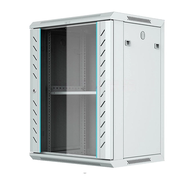
Electrical enclosure sizes are not universal, but most manufacturers follow common size families. This guide explains typical wall-mount and floor-standing dimensions, how to read catalog sizes, and how to choose the right enclosure size for your layout. There is no single global chart for standard. A “Core” is an item that can be remanufactured using replacement parts. Exchange: We ship your order now, and you send us your core within 30 days to get the core charge refunded. Outright: We ship your order now. There is no need to send us a core. Advanced Exchange Required: Y ou must send in a. Whether it's a small electrical breaker box in a residential property or a panel medium voltage cabinet in industrial environments, selecting the right type, size, and configuration is critical. This guide explores control panels, electrical boxes, breaker panels, bus bars, junction boxes, and. Plastic Electrical Box, also known as a consumer control unit or electricity control unit. It is a device that is a type of distribution board that helps in protecting cables from overload and then damage or accidents. Installation: Flush Mounted. JUNON new range: C6 series Single Phase. IEC 62262 IK10. of national committee technical been bodies). established committees. The work of preparing International t e right Electrotechnical interested in federation on a subject committee.
[PDF]

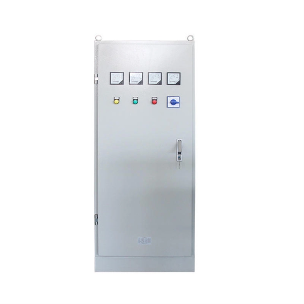
Nauru's Online Legal database contains copies of Nauruan legislation (Acts and Subsidiary legislation), court decisions, gazettes and other relevant documents. Copyright 2023 — Ronlaw. Developed & Maintain by Digitity - Powered by Datec DocSearch™ Enhanced Search. The XL type low-voltage power distribution cabinet uses domestically designed new components. The enclosure is made of bent steel plates, featuring a compact structure, easy maintenance, and flexible circuit scheme combinations. Besides air circuit breakers and fuses for circuit protection, the. Access the most up to date content in ISO standards, graphical symbols, codes or terms and definitions. Preview content before you buy, search within documents and easily navigate between standards. RONLAW stands for Republic Of Nauru Law. Developed &. Frequency, voltage and meter accuracy standards 8. of a public supplier's works 9. Promotion of efficiency and economy 10. Codes of Practice 11. Location of meter box 13. Conductors from isolator switch to. REV. The online standards review database has been updated to provide greater functionality, offering a single sign in feature with dashboard, so users can easily access and highlight those items that require attention. The new system reduces staff and volunteer time by allowing committees to do all of.
[PDF]
95 % (Minimum), Pb, Sb, Oxy. 0010 As per BS EN 13601:2018. Corner radii, however can be customized to the customer's requirements. (Full Round edges can be provided in case required by the customer). Cu + Ag - 99. This article explains how the calculator works, the standards it follows (IEC and NEC), and what factors influence. In power engineering, particularly within low-voltage switchgear and packaged substations, copper busbars are the vital conduits for energy transmission. Their precise specification directly impacts a system's safety, reliability, and economic viability. This crucial component demands careful. WILLELE provides high-quality copper comb busbars and DIN rails for reliable circuit connection and modular panel assembly. Our phase distribution and circuit breaker busbars ensure excellent conductivity and precise spacing, while DIN rails are made from galvanized steel or aluminum for easy and. Drawing on international standards, long-term field data, and enclosure-level design experience, we clarify best practices for copper busbar joints —helping designers, engineers, and project managers make safer and more cost-effective decisions. Many engineers assume that increasing the busbar. Select the busbar Material (Copper or Aluminum). Adjust the Safety Factor if needed (default is 25%). Full IEC Verification Enter your base parameters as in the standard method. This. Cu + Ag - 99.
[PDF]
It is suitable for indoor lighting and power distribution circuits with an alternating current frequency of 50 Hz, a single-phase voltage of 240 V, a three-phase voltage of 450 V and below, and a current of up to 250 A. XM series indoor lighting distribution box is designed for AC 50Hz, 220V or 380V terminal circuits with rated current ≤100A. It provides comprehensive protection against electric leakage, short circuit, and overload. Common installation methods include surface mounting and recessed mounting. Widely. XM Cabinet is widely used in lighting distribution systems of power station,transformer station,factory,mine,hotels,apartment,buildings,port,railway station,airport,warehouse,hotels etc. This comprehensive guide delves into the features, benefits, and practical applications of XM Low Voltage Lighting. The Low Voltage Distribution Box is a compact and reliable solution for secondary power distribution in industrial, commercial, and residential applications. They can be designed for either surface-mounted wall installation or.
[PDF]


