Plugs directly into Polaris Pulse System for switch lighting and keyed on ignition. Made in the USA! Activates High current relay when High Beams are turned on, used to add large light bars and driving lights without having to install additional switches in the dash. Made in the USA!. $ 46. 00 Original price was: $46. Upgrade your Polaris with the XTC Power.
[PDF]
If your high beams are not working, the most likely cause is a blown fuse or a burned-out bulb — both of which you can check yourself in under 15 minutes. That said, there are seven possible culprits, ranging from simple fixes you can handle at home to electrical faults that need a mechanic's. To be clear, I am not saying the highbeams are turning on and off, I mean the actual intellibeam system as indicated by the headlight symbol with the "A" in it on the DIC. When the system is on, the highbeams most of the time will work 100% as expected activating and deactivating when appropriate. Automatic high beam (AHB) systems, sometimes marketed under proprietary names like IntelliBeam or SmartBeam, are designed to enhance nighttime visibility by automatically switching between high and low beams. These systems use forward-facing cameras or sensors to detect light sources from oncoming. Affiliate programs and affiliations include, but are not limited to, the eBay Partner Network. 2021+ Ford F150 Discussion of the 14th generation F150. LED headlight High Beam Failure noticed that high beam on the drivers side LED headlight stopped working. Hooked up the reader and found fault code. Auto High Beam is a safety feature that controls the headlight operation and lights up the road in front using low and high beams. There is too much lag time for enabling the high beams. I just use the old skool manual headlights mode and switch my high beams as.
[PDF]
This tariff finder is designed to help goods exporters and importers maximise benefits from New Zealand's Free Trade Agreements (FTAs) and compare tariffs in more than 110 other international markets. The Working Tariff Document of New Zealand (WTD) has had recent updates, effective 1 April 2026. Goods exporters and importers can use it to check the tariff rate for over 167 World Trade. The average cyclic hydrocarbons import price stood at $1,494 per ton in 2023, shrinking by -12. 2% against the previous year. Over the period under review, the import price showed a slight downturn. The pace of growth was the most pronounced in 2021 when the average import price increased by 42%. Prices effective from 1st January 2026 are outlined below. All charges are exclusive of GST. Select here for the current Super Yacht Ad-Hoc Marine service charges. Settlement prices on instruments without open interest or volume are provided for web users only and are not published on Market Data Platform (MDP). These prices are not based on market activity. Effective 01 DEC 2023 Shipments from / to USA and U.
[PDF]

In this tutorial, I will show you how you can connect the Optocoupler to Arduino, read the data as Analog or Digital, and if necessary convert the analog values to digital, and how to reduce noise from the sensor. The Infrared Slotted Optical Optocoupler Module is a device that uses infrared light to transmit signals between two electrically isolated circuits. It consists of an infrared emitter (LED) and a photodetector (phototransistor) housed in a slotted enclosure. When an object passes through the slot. Slotted Optocouplers (Photo Interrupters) are very useful sensors, often included in Arduino projects to detect position of moving objects, measure speed of rotation, or linear motion, frequency of events, and many others. They are easy to use, but it is important to understand how they work, so. This tutorial is a comprehensive, practical guide to the Speed Sensor / Tacho Sensor (Slot-Type Optocoupler) (Leobot Product #245). Moreover, a simple application is programmed that shows how to wire and how to program an Arduino when working with the module. In this tutorial, the module is used as an “digital input board”. If you want to use the. In this project, I will talk about Phototransistor Optical Interrupter Switches (Opto Coupler) Module, how this module works and helps in determining the speed of a rotating object and finally I will show you how to Interface Optical Interrupter Switch Sensor with Arduino and measure the speed of a.
[PDF]

The wavelength of the 40G QSFP+ SR4 optical module is 4x850nm, while the 40G QSFP+ LR4 optical module adopts CWDM coarse wavelength division multiplexing technology, with four wavelengths of 1271nm, 1291nm, 1311nm, and 1331nm. The fiber type and connector are different. 40GBASE-ER4 is a long-reach 40GbE optical standard that delivers 40Gbps transmission over single-mode fiber up to 40km using QSFP+ transceiver. It achieves this reach by multiplexing four CWDM optical lanes into a duplex LC fiber interface, allowing long-distance connectivity without requiring. While 100G and 400G technologies continue to advance, 40G QSFP+ optical modules remain a mainstream, cost-effective solution for upgrading small to medium-sized data centers. It is commonly deployed in data centers, enterprise backbone networks, and metropolitan area networks where stable, high-speed transmission over extended distances is. In the deployment of 40G networks, the 40G QSFP+ optical module is one of the most widely used, defined by IEEE 802. The two basic interface specifications for QSFP+ optical modules are 40G BASE-SR4 and 40G BASE-LR4. In this blog, ETU-LINK will talk about. The QSFP+ module is designed for use in 40GBASE Ethernet throughput up to 10km, 30km or 40km over single mode fiber (SMF) using a wavelength of 1310nm via duplex LC connectors. This transceiver is compliant with QSFP+ MSA and IEEE 802. Digital diagnostics functions are also available.
[PDF]
GIGALIGHT 800G QSFP-DD SR8 is a hot-pluggable optical transceiver module designed for 800G SR8 Ethernet links in data centers. It adopts 100G PAM4 and VCSEL technology and can realize 800G data exchange within 100m. 800G OSFP/QSFP-DD | Transceiver Modules - FS FS United StatesFREE SHIPPING on Orders Over US$79 Contact Us United States / $ USD All Products Solutions Services Resources Contact Us FREE SHIPPING on Orders Over US$79 United States Home Optical Transceivers Ethernet/RoCE Networking 800G. Cisco QSFP-DD and OSFP 800G ZR/ZR+ digital coherent optics modules enable 800G traffic over amplified Dense Wavelength-Division Multiplexing (DWDM) links up to 120 km for 800ZR and over 1000 km for 800G ZR+. Cisco ® QSFP-DD and OSFP 800G ZR/ZR+ coherent optics modules enable 800G traffic over. Your request has been submitted successfully. Our sales manager will contact you soon. High-density 800G OSFP and QSFP-DD transceivers support InfiniBand and RoCE, enabling 100m to 2km transmission via MMF and SMF. Have any questions? Talk with us directly using LiveChat. It is compatible with most switches(CISCO, Juniper, Arista,Brocade,H3C,HPE, DELL, etc) OSFP 800G SR8 is an Eight-Channel, Parallel, Pluggable, Fiber-Optic OSFP for 800Gigabit.
[PDF]

Optical Modules Market Segments - by Product Type (Transceivers, Receivers, Transmitters, Amplifiers, and Others), Application (Data Centers, Telecommunication, Enterprise Networking, and Others), Distribution Channel (Online Stores, Direct Sales, Indirect Sales . Optical Modules Market Segments - by Product Type (Transceivers, Receivers, Transmitters, Amplifiers, and Others), Application (Data Centers, Telecommunication, Enterprise Networking, and Others), Distribution Channel (Online Stores, Direct Sales, Indirect Sales . Data centers will keep dominating optical module demand as AI and cloud drive revenue growth through 2030. Optical module demand is being pulled in two directions at once, faster bandwidth for dense networks and tighter constraints on power, security, and lead times. 8% during the forecast period 2025-2031. The potential shifts in the 2025 U. tariff framework pose substantial volatility. The Optical Module Market size was estimated at USD 26. 53 billion in 2025 and expected to reach USD 30. The accelerating explosion of global data traffic has thrust optical modules into the heart of modern communications.
[PDF]
Connectorized attenuators often have a quite compact housing, essentially looking like a fiber-optic adapter. Some of these devices provide a fixed level of attenuation, quantified as the insertion loss in decibels. An optical attenuator, or fiber optic attenuator, is a device used to reduce the power level of an optical signal, either in free space or in an optical fiber. The basic types of optical attenuators are fixed, step-wise variable, and continuously variable. Optical attenuators are commonly used in. Fiber-optic attenuators are a specific type of optical attenuators which are used in fiber optics, e. for achieving a suitable signal level for a data receiver in a telecom system. It primarily ensures the power or amplitude of a signal is lowered without significantly distorting its waveform. The attenuator circuit will allow a known source of power to be reduced by a predetermined factor, which is usually expressed as decibels.
[PDF]

As core components of optical communication systems, the proper installation and use of optical modules directly impacts network stability. The customer has 2 alarms on BTS3900 (GSM-R network). BBU Optical Module Transmit/Receive Fault 2. RF Unit Maintenance Link Failure The results of this alarms was restarting of the RF unit. After combining the RRU log analysis and the alarm of the optical module, the radio frequency maintenance. An alarm is generated when the transmit or receive power of an optical module is out of the allowed range. Indicates the MIB object ID of the alarm. Indicates the parent. After ruling out traditional problems like passive intermodulation (PIM), poorly aimed antennas and/or other coaxial problems, dirty fiber connectors account for 60 to 75% of the alarms, failures, and poor throughput problems found in modern cellular systems today. It has been several years since. All or part of the products, services and features described in this document may not be within the purchase scope or the usage scope. About This Document Introduction This document describes the routine hardware maintenance of the BBU3900. This article systematically identifies common anomalies during optical module installation. Combining hardware principles with practical experience, it.
[PDF]

Average Optical Power: How bright the light is (measured in dBm). Too dim? Your signal gets lost in the fiber. Extinction Ratio: The difference between “on” (1) and “off” (0) light power. A higher ratio = cleaner signals. Transmitter Side: An electrical signal hits a laser diode (LD) or LED, which spits out light. Receiver Side: Light enters a photodetector (like a tiny solar cell), which turns it back into electricity. A built-in amplifier boosts the signal for your. The average transmitted optical power refers to the optical power output by the light source at the transmitting end of the optical module under normal working conditions, which can be understood as the intensity of light. In communication, we usually use dBm to represent optical power. However, in practical use, we adopt the average Tx power. The transmission power is related to the. This article provides an in-depth analysis of two key performance indicators of optical modules: transmitter power and receiver sensitivity. Transmitter power characterizes the average optical power output from the laser under rated conditions, while receiver sensitivity indicates the minimum. An optical module is a connecting module that serves as an optical-electrical conversion device. At the receiver end, the optical signals are reconverted into electrical.
[PDF]

Wavelength measurement devices work on the principle of measuring the distance between two consecutive points of an electromagnetic wave in terms of wavelengths. This can be achieved through various methods, including spectrophotometry, interferometry, or the use of optical spectrum. These devices accurately determine the wavelength of light, providing crucial information for research, quality control, and diagnostics. Wavelength is a fundamental property of light and can significantly affect its interaction with matter. Precise wavelength measurement allows scientists to. Wavelength meters are interferometers used to measure wavelengths of laser beams. The devices are mounted on benches or desktops. They generate numerical values identifying pulsed and continuous wave lasers. They enable. This article provides a comprehensive explanation of the concept of wavelength in physics, particularly in optics and photonics. It defines wavelength as the spatial period of a wave, explaining its mathematical relationship to the wavenumber, optical frequency, and phase velocity. Accurate wavelength measurement is crucial in fields like physics, chemistry, astronomy, and engineering. Each method offers unique insights and varying degrees of precision.
[PDF]
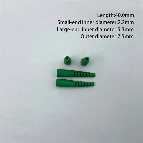
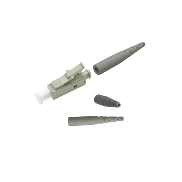
Fiber optic connectors in SFP modules are the physical interfaces that connect the transceiver to fiber patch cables, enabling optical signal transmission between network devices. Fiber optic connectors are silently the hero that make fiber networks to have secure, low loss, and easy maintaining connections. In their absence, it would be the only possible approach, splicing that is, which, indeed, is costly and time consuming besides irreversible. These connectors play a. A fiber optic connector is a mechanical device used to align and join optical fibers, enabling light to pass through with minimal loss. This allows for quickly connecting and disconnecting of fiber optic cables without splicing.
[PDF]

A constant trend in optical modules is to offer higher data rates within the size-limited and thermally-limited form factor by using smaller, integrated Power and Data-Converter solutions. The SFP module is a hot-pluggable optical transceiver used for connecting network switches. It converts electrical signals to optical signals and vice versa. For the 1G SFP module, it is primarily divided into the following two categories: Optical SFP Transceiver Optical transceiver connection RJ45. The optical module serves as a crucial component in optical fiber communication systems, operating at the physical layer, which is the lowest layer in the OSI model. An. Optical modules and media converters are both key photoelectric conversion devices widely used in fiber optic communication, data centers, enterprise networks, and broadband access systems. Many users are confused about their roles, differences, and connection rules. This article will clarify. Microwave photonics technology (MWP), which has been applied to various radar, Telcom, Electronic Warfare systems, is now facing more and more challenging development trend of miniaturization and modular array for increasing node counts and system complexity.
[PDF]
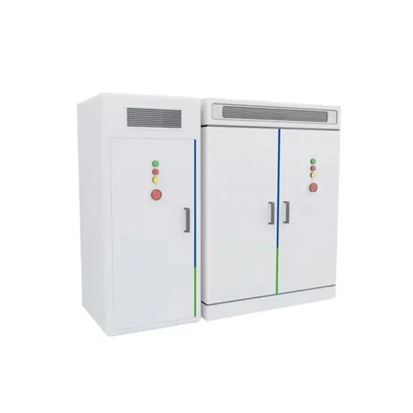
Lighting Control System | Smart Lighting Wiring Setup | Full Guide In this video, you will learn how to connect and install a Lighting Control System step-by-step. This guide covers wiring setup, switch modules, dimming control, sensor setup and panel . as a guide for proper and reliable installation. The mounting location should e selected and prepared based on the application. All electrical wiring and mounting hardware (i. ) should be prepared with consideration of the requirements o cuit breaker before. Intelligent Lighting Controls' installation guides provide detailed instructions on how to install all of our solutions. The Lightolier Controls Optio Lighting Control Panels are high-performance, wall mounted lighting control panels which offer a wide range of dimming and relay modules to accommodate any lighting control application.
[PDF]

First, inspect the optical module appearance for physical damage, cracks, missing components, poor solder joints, or burn marks. Next, compare voltage, resistance, and waveform parameters between a normal it and the suspected faulty one, both in powered and unpowered states. As core components of optical communication systems, the proper installation and use of optical modules directly impacts network stability. This article systematically identifies common anomalies during optical module installation. However, during installation and daily operation, various issues may arise. The following will introduce the causes of various problems and how to deal with them. Optical module method/step 1. During the test, the value of the module I BiasADC is 0, and the TXLOP-ADC and. These compact devices convert electrical signals to optical signals and vice versa, enabling data transmission over fiber optic cables. While generally reliable, failures do occur, leading to frustrating downtime, performance degradation, and costly troubleshooting. This comprehensive guide details. Have you ever dealt with sudden network drops from faulty optical modules? Issues like this cannot only break communications, but they can really jeopardize business continuity.
[PDF]