Proper planning for installing cable tray includes calculations based on loading, support systems, cable/wire fill and spacing, conductor types, securing of the cables and wire, and proper grounding and bonding are all important aspects of cable tray installation. How about organizing your wiring with a cable tray system? Smart move. Whether you're building a commercial setup or upgrading an industrial plant, proper cable tray installation ensures neat wiring, safe access, and easy maintenance. This guide covers the critical steps, from selecting the right electrical cable tray and performing accurate cable fill. Cable tray installation implies the construction of an electric road that will be safe. In order to get it right, installers are supposed to adhere to a plan that ensures that wires are kept cool and the building is stable. The beginning of success is to review the Bill of Quantities (BOQ) so that. Our solutions and products are made in the USA and our service and support can assist with any install or product selection questions that you may have. Here's what you'll learn: Planning: Assess cable requirements, calculate loads, and select the right tray system (ladder, trough, or wire mesh) based on factors like weight and environment. Proper installation of cables in trays is critical for maintaining an efficient and safe electrical system. This is why proper planning and execution are.
[PDF]
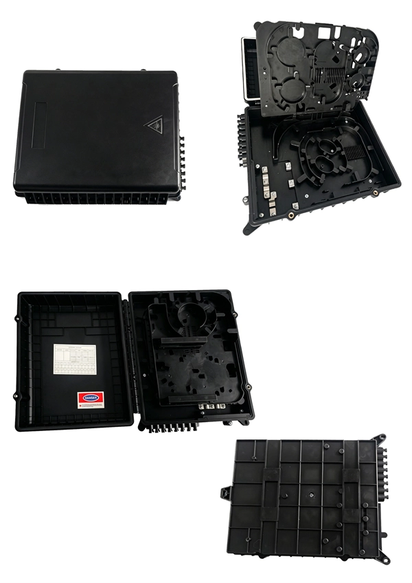
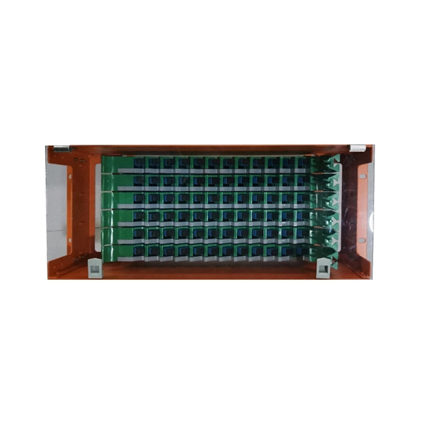
Junction Boxes for fiber optic cable shall be placed along the fiber optic conduit and should be spaced a minimum of every 1500' for Limited Access and non-Limited Access roadways and at all signalized locations or proposed signal locations. Introduction to Fiber Optic Junction Boxes A fiber optic junction box, also known as a fiber optic distribution box or termination box, is a protective enclosure that facilitates the connection and management of fiber optic cables. It serves as a central point for organizing and distributing. Fiber junction boxes play a crucial role in the organization, protection, and distribution of fiber optic cables in various applications, including telecommunications, data centers, and industrial networks. These boxes serve as connection points for fiber optic cables and facilitate efficient cable. A Fiber Terminal Box (FTB) is a customer-side termination and distribution device used at the end of the optical network. These enclosures are essential for protecting fiber connections from environmental hazards and physical damage. As the demand for high-speed internet and reliable telecommunications increases, the. The Fiber Optic Association, Inc. (FOA) was founded in 1995 to help develop the workforce to build the fiber optic networks to support a rapid expansion in communications and the Internet. It houses and protects the connections and terminations of fiber optic cables, providing a central point for managing and organizing the fiber.
[PDF]

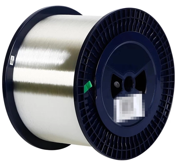
This guide breaks down their technical differences, performance metrics, real-world applications, and how to choose the right one for your network—all optimized for Google SEO and packed with actionable insights. Introduction: Why Fiber Optic Cable Type Matters. Single mode fiber optic cable is made up of a small diameter glass or plastic core surrounded by cladding, which is a layer of reflective material. This small diameter core, typically around 9 microns in diameter, allows only one mode of light to pass through, resulting in a narrower beam of light. But not all fiber cables are created equal: multimode (MM) and single mode (SM) fibers are the two primary types, each engineered for specific use cases, from short-range data center connections to transcontinental telecom backbones. Whether you are an IT specialist, a network manager, or just a curious individual interested in the. As explained by the Fiber Optics Association, fiber optics is the communications medium that sends optical signals down hair-thin strands of extremely pure glass cores. The core is surrounded by the cladding that traps the light in the core. Fiber types are identified by the diameters of the core. The article compares single-mode and multimode fiber optic cables, especially in how their core design, light propagation, and use-cases differ. Core Diameter Single mode fiber: one that has a small light-carrying core that is about 9 micrometers (µm) in diameter.
[PDF]
This guide walks you through a safe, code-aware way to add a weather-ready receptacle near planting beds or a patio. If local rules differ, follow your jurisdiction's code and pull a permit when needed. Pick a spot that keeps the box out of splash zones and mower paths. Installing an outdoor GFCI receptacle in a garden takes planning, code-rated parts, and safe wiring in conduit or UF cable. Great for adding outlets, lighting, or appliances outside. more Need outdoor power? In this video, I'll show you how to install a weatherproof outdoor. Installing an outdoor electrical outlet can significantly enhance the functionality of your outdoor space, making it easier to power tools, lights, and appliances without fuss. This article details the process of installing them, which helps you comprehend distribution boxes. This comprehensive guide will equip you with the expert knowledge to safely install your outdoor electrical box, from understanding crucial wiring tips and essential GFCI protection to implementing industry best practices. Let's illuminate your outdoor projects, the right way. However, proper installation is essential for safety and local code compliance. The good news is that you don't need.
[PDF]
In this guide, we will provide you with a step-by-step process to help you wire an electrical panel box safely and efficiently. Before you begin wiring an electrical panel box, it is important to gather all the necessary tools and materials. An electrical panel box, also known as a breaker box or a distribution board, is a crucial component of any electrical system. It serves as a central hub for distributing electricity throughout a building, ensuring that power is delivered safely and efficiently to all the required locations. In part two, learn how to install recessed lighting. Begin by laying out your lights templates. Shut off the power at the circuit breaker box. Drill holes in the ceiling, run the wiring, run the cable into the new box, mount the light and enjoy. Whether you are an electrical contractor or a construction brigade, knowing how to properly and safely install distribution boxes is the basis of ensuring the safe operation of the entire system. To understand how a breaker box works, it is helpful to. Hey, in this article we are going to see the Single Phase Distribution Box Wiring Diagram and Connection Procedure. And all the switching and protective devices are installed in the. Understanding load center wiring diagrams is essential for anyone who is involved in electrical installations or repairs. These diagrams provide a visual.
[PDF]

Wiring an electrical panel box can seem like a daunting task, but with the right knowledge and tools, it can be done successfully. In this guide, we will provide you with a step-by-step process to help you wire an electrical panel box safely and efficiently. Distribution Board or DB is an electricity supply system or a common enclosure that distributes the electrical power feed into subcircuits. It includes isolator, RCCB (Residual current circuit breaker) or RCD (Residual-current device) devices, protective fuses or MCB's (Miniature Circuit Breaker). This book serves as a concise guide for learners interested in basic electrical house wiring concepts. It provides practical instructions for various electrical configurations and connections, emphasizing the importance of safety and proper installation. Additionally, it introduces essential. The Guidelines For Electrical Wiring In Residential Buildings has been prepared as a wiring guide for all Wiremen and Electrical Contractors for undertaking electrical wiring in residential buildings to conform to the Electricity Regulations 1994. The Guidelines are prepared in a concise and. An electrical panel box, also known as a breaker box or a distribution board, is a crucial component of any electrical system. All the electrical sub circuits are originated from a Distribution Board. To understand how a breaker box works, it is helpful to.
[PDF]
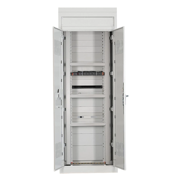
Free electrical calculators for wire sizing, voltage drop, load calculations, conduit fill & power factor. NEC compliant tools for electricians & engineers. In this guide, we'll break down everything you need to know to install a distribution box correctly and confidently. Choose the right box based on environment (indoor/outdoor), load capacity, and durability. Check for proper IP/NEMA ratings and material quality. Ensure safe placement: install in. Professional electrical wire sizing tool based on National Electrical Code (NEC) standards. Calculate proper wire gauge, voltage drop, and ampacity for safe electrical installations. Input your electrical parameters to get accurate wire size. Pro Insight: A well-planned distribution box feels like a silent partner—you only notice it when something's wrong. Our goal? Make sure you never notice it. Before we dive into calculations, let's get familiar with a few essentials: 1. Create accurate bids and win more projects with automated formulas. The sizing requirements for pull boxes, junction boxes, handhole enclosures, and conduit bodies exist to prevent conductor insulation damage. Those requirements are in 314. 28, and they apply to all conductors 4 AWG and larger (Fig. To illustrate how these requirements prevent conductor. Estimate wire ampacity with derating factors for temperature and conduit fill. Reference tool based on NEC guidelines. It is NOT a substitute for professional.
[PDF]
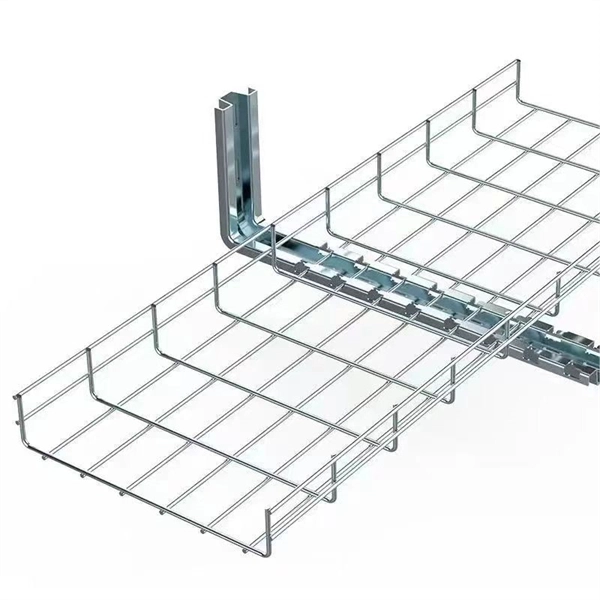
Students trading aid on how best to put an internal 90 degrees bend in steel cable tray. Videos are training aids for City and Guilds 5357 (C and. The bends, tees, crosses, risers and reducers of wire mesh cable tray can be easily and quickly made live at the project by using a bolt cutter. Since the jaws of the bolt cutter drags a layer of zinc across the cut end and forms a protective layer. When a wire cable tray is cut, the fact that a. You can buy a manufactured 90 degree bend or make one on a cable tray bending machine but in this video I show you how to make one using a metal bar. Electrical UK Wiring == 🕐. How many wires can fit in one tray? One should never fill up a tray. The general safety regulations state th/at a person is advised to fill 40-50 percent of the available space. The reason behind this is that the electricity-carrying wires become hot. This involves a few essential steps to ensure a successful bending process. Each example of bends and tee's clearly illustrate proper tray cutting combined with recommended usage of Cablofil accessories. Engineers and contractors in North America and around the world have found. The first step is to mark out the tray (A). Construction of a flat 90° bend (A) The amount of tray lip to be removed is equal to 2, 3/4 the width of the tray, half of this measurement will be removed on either side of the centre line. To remove the lip we can use a small hand grinder (B) or a file.
[PDF]
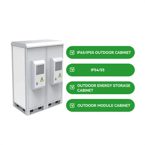
The distribution box is a crucial piece of equipment that connects solar panels to the AC power grid. Solar energy is a clean, renewable, and pollution-free source. A Solar Distribution Box plays a critical role in managing, controlling, and distributing electrical power safely within solar systems. Without it, the risk of electrical faults, system failures, and energy loss increases significantly. As solar adoption continues to rise globally, understanding. A panel junction box is typically mounted on the back of a solar module. It serves as the module's protected connection point—housing internal electrical terminations and enabling safe, standardized external connections via connectors. A PV combiner box is installed at the system level. Its primary. In modern solar PV installations, multiple strings of solar panels generate direct current (DC) power that must be safely consolidated, routed, and protected before it reaches the inverter. Handling high-voltage DC electricity requires precision and uncompromised safety measures. This essential device incorporates sophisticated protection mechanisms and monitoring capabilities to ensure.
[PDF]

How to Use Optical Power Meter TR-504 | Optical Power Meter Working| Testing OPM, VFL, RJ45 | TRICOM In this video, we walk you through how to use the TRICOM TR-504 Optical Power Meter and explain how it works. Learn how to test fiber optic cables, OPM, VFL . Optical power meters are a key element in the optimization and maintenance of such optical networks and of their components. In this article, learn: What is an optical power meter? An optical power meter (OPM) measures the power levels of light signals in devices that transmit data or power using. An optical power meter measures the strength of light traveling through a fiber optic cable, giving you a reading in dBm (decibels relative to one milliwatt). The basic process is straightforward: turn the meter on, set it to the correct wavelength, clean your connectors, plug in, and read the. OPM interface: insert the fiber to be tested, test the optical power. An optical power meter is a tool that measures the number of optical power in a cable is fiber-optic. It helps engineers verify the performance of optical fiber systems, ensuring that the signal strength meets requirements, and is an essential tool for communication network maintenance and troubleshooting.
[PDF]
Junction box costs range from low‑price indoor models ($10‑$60) to weatherproof units ($70‑$450), with installation averaging $100‑$300 depending on location and materials. If you're planning any electrical work, one of the small but important items on your list will be the. How can we improve? Choose from our selection of junction boxes, including over 2,800 products in a wide range of styles and sizes. Same and Next Day Delivery. Electrical Junction Box, Ventilated Design, Cable Grommets, Indoor/Outdoor Use with Mounting Panel & Hinged Cover. (Grey Cover, 13"x13"x5. 1") Need help? Discover flame-retardant, weatherproof junction boxes to safely encase electrical splices. At first. These cast aluminum clamp type signal bases are available as plain split bases or with one or both halves having a cast-in junction box capable of holding a bakelite terminal strip of 6 units (12 binding posts). ZIP code to view pricing. ZIP code to. Find gifts for the greatest mom. Shop Now > Find Steel junction boxes at Lowe's today.
[PDF]
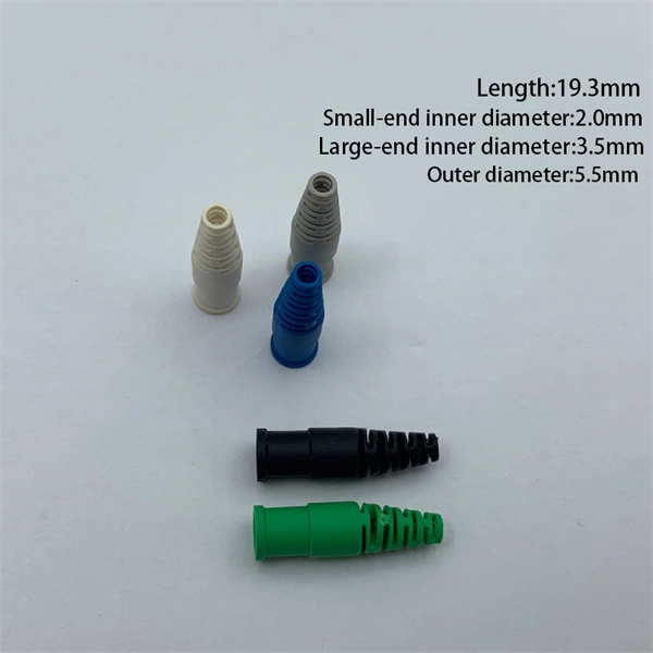
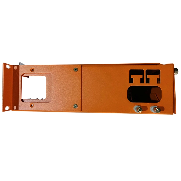
Learn how to install a fiber optic termination box step-by-step for FTTH projects. Covers mounting, splicing, routing, labeling, and testing for indoor/outdoor use. Installing a fiber optic termination box is one of those jobs that looks simple on paper, but it's easy to do poorly in the field. If you do not have relevant experience and skills, it is recommended to ask a professional to install it. Preparations: Before installation. How to install the FTTH terminal box? - YouTube This kind of box are used in the end termination or residential building sand villas, to fix and splice with pigtails, can be installed on the wall. When it comes to ONT installation, you've got two main options: Indoor ONTs are installed inside your home, typically in a utility room, basement or another centralized spot. Both options have their advantages, and the choice. A fiber termination box is the standard instrument used in fiber optic networks to connect, secure, and protect optical fibers at the terminating point. To install a junction box correctly, choose a box that matches the wiring method and environment, mount it securely, bring cables in.
[PDF]

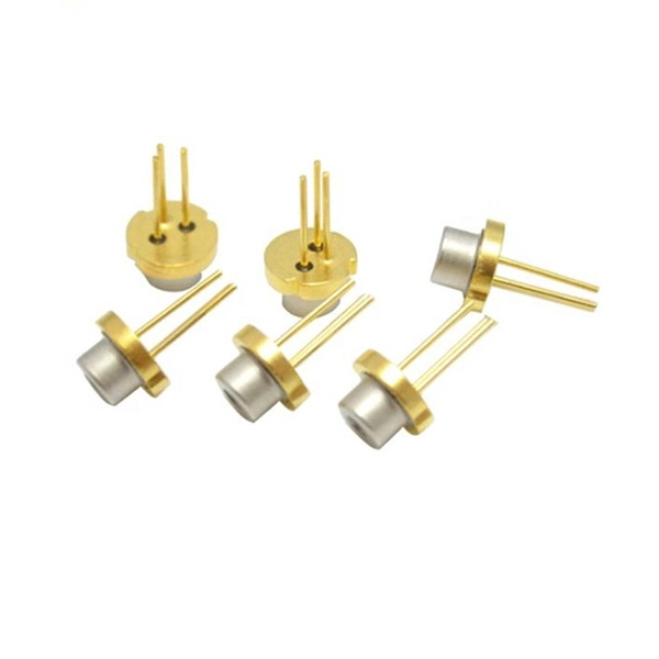
This comprehensive guide breaks down the internal structure, core components (TOSA, ROSA, lasers), and operational mechanisms of SFP optical modules, enriched with technical insights and real-world applications. Optical Modules (also known as Optical Transceivers) are critical components in fiber optic communication systems. As the core optoelectronic devices operating at the Physical Layer of the OSI model, their primary function is to perform electro-optical and photo-electric conversion during signal. In the era of 5G, AI, and high-speed data centers, optical modules serve as the core bridge for converting electrical signals to optical signals (and vice versa), enabling fast, reliable data transmission across networks. They are used in fiber optic communication systems to transmit data over long distances with minimal loss and interference. This article systematically identifies common anomalies during optical module installation. Combining hardware principles with practical experience, it. When the industry speaks of optical modules, it refers specifically to small, hot-swappable packaged optical modules, which are used on equipment ports and can be hot-swapped during operation, and are mainly used to convert the electrical signals in equipment (usually switches or router equipment).
[PDF]
This guide covers the critical steps, from selecting the right electrical cable tray and performing accurate cable fill calculations to managing a safe cable pull through and ensuring all bonding and grounding requirements are met. Article Summary: A compliant cable tray installation requires a thorough understanding of NEC Article 392, proper structural support, and precise installation techniques. But before you lay the first tray or clamp down a single cable, you need a solid plan. This guide breaks down the process step by step. Here is a step-by-step guide on how to install a standard metal cable tray system (e., ladder or perforated type). Before starting, ensure you have. NEMA VE2 addresses cable tray installation and provides information on maintenance and system modification. NEMA VE2 was developed by the NEMA Cable Tray Section, of which MP Husky is a charter member. Ladder Cable Trays Solid side rail protection and system strength with smooth radius fittings and a wide selection of materials and finishes. Maximum strength for long span applications. Welcome to our step-by-step guide on installing cable trays! In this video, we'll explore the different types of cable trays available and provide detailed instructions for their installation. Whether you're an experienced electrician or a DIY enthusiast, this video is perfect for you.
[PDF]
Step-by-step on-site guide: learn how to plan, mark, support, and install cable trays correctly, from shop drawing approval to final checks. Method Statement installation of Cable Trays and Ladders - Planning Engineer FZE. The Cable Tray system is installed in electrical rooms, plant rooms, and service. Whether you're building a commercial setup or upgrading an industrial plant, proper cable tray installation ensures neat wiring, safe access, and easy maintenance. But before you lay the first tray or clamp down a single cable, you need a solid plan. This guide breaks down the process step by step. In order to get it right, installers are supposed to adhere to a plan that ensures that wires are kept cool and the building is stable. The beginning of success is to review the Bill of Quantities (BOQ) so that. In this post, we will see together how to install cable tray on-site. Firstly, we need an approved shop drawing that shows the cable tray route, its dimensions, installation height, support system, the number of layers of these trays, and the type of systems they will serve. The key requirements for cable tray installation include: Incorrect installation can lead to overheating, cable damage, or system failure. This guide covers the critical steps, from selecting the right electrical cable tray and performing accurate cable fill.
[PDF]