Rayleigh scattering -based distributed acoustic sensing (DAS) systems use fiber optic cables to provide distributed strain sensing. In DAS, the optical fiber cable becomes the sensing element and measurements are made, and in part processed, using an attached optoelectronic device. These systems enable precise measurement of temperature, strain, and acoustic signals along the entire length of an optical fiber. DFOS technology plays a crucial. ONYXTM the flagship platform from Sintela now delivers a customizable all-in-one, simple and cost-effective solution for your distributed fiber-optic sensing needs. Representing the next step in the evolution of Distributed Fiber Sensing, ONYX™ converts existing telecommunications fiber-optic cable. Distributed acoustic sensing systems (DAS) are fiber optic based optoelectronic instruments which measure acoustic interactions along the length of a fiber optic sensing cable. The unique feature of a distributed acoustic sensing system is that it provides a continuous (or distributed) temperature. Distributed Acoustic Sensing (DAS) is a cutting-edge technology that uses optical fiber to sense and identify multiple parameters over extended distances remotely. The technology leverages the Rayleigh backscatter theory to detect vibrations and sounds along the fiber Fiber optic-based Distributed.
[PDF]

Distributed Fiber Optics Sensing (DFOS) is a mature technology, with known, tested, verified, and even certified performance of various interrogators and measurement methods, which include Distributed Temperature Sensing (DTS), Distributed Temperature-Strain Sensing. Distributed Fiber Optics Sensing (DFOS) is a mature technology, with known, tested, verified, and even certified performance of various interrogators and measurement methods, which include Distributed Temperature Sensing (DTS), Distributed Temperature-Strain Sensing. Distributed Fiber Optics Sensing (DFOS) is a mature technology, with known, tested, verified, and even certified performance of various interrogators and measurement methods, which include Distributed Temperature Sensing (DTS), Distributed Temperature-Strain Sensing (DTSS), and Distributed Acoustic. FEBUS Optics is the world reference in DFOS, distributed fiber optic sensing systems (DAS, DTS and DSS), to reduce the environmental impact of human activity, protect people, and optimize production. FEBUS provides state-of-the-art devices and turnkey solutions based on its patented technologies.
[PDF]
Data drift in fiber optic vibration sensors can stem from a variety of sources. Understanding these causes is the first step toward effective troubleshooting: 1. Environmental Factors: Changes in temperature, humidity, and pressure can affect the performance of fiber optic sensors. Fiber-optic sensing (FOS) technology has emerged as a cutting-edge research focus in the sensor field due to its miniaturized structure, high sensitivity, and remarkable electromagnetic interference immunity. Compared with conventional sensing technologies, FOS demonstrates superior capabilities in. Fiber optic vibration sensors have become critical components in various industries, including oil and gas, structural health monitoring, and security systems. However, like any advanced technology. REVIEW www. com Optical Fiber Sensors: Working Principle, Applications, and Limitations Mohamed Elsherif,* Ahmed E. Salih, Monserrat Gutiérrez Muñoz, Fahad Alam, Bader AlQattan, Dennyson Savariraj Antonysamy, Mohamed Fawzi Zaki, Ali K. Yetisen, Seongjun Park, Timothy D. Identifying and resolving issues in fiber optic systems helps maintain peak performance and reliability. Regular inspection, maintenance, and adherence to standards and best. Initially conceived as a medium to carry light and images for medical endoscopic applications, optical fibers were later proposed in the mid 1960's as an adequate information-carrying medium for telecommunication applications.
[PDF]
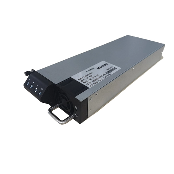
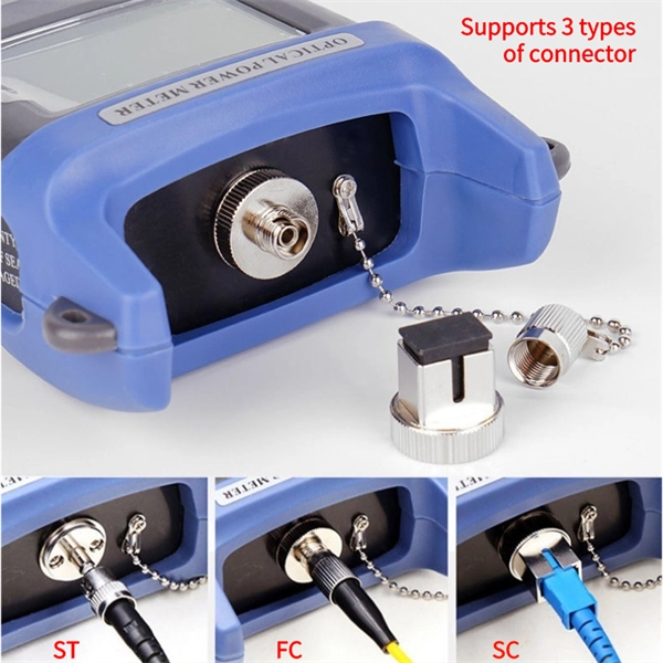
The PL-1000D simultaneously monitors up to 16 fiber strands, eight on the OTDR and eight on the OSA, and operates standalone over dark fiber, lighted fiber, or a third party network without impacting network traffic. The device monitors the entire D. The PL-1000D simultaneously monitors up to 16 fiber strands, eight on the OTDR and eight on the OSA, and operates standalone over dark fiber, lighted fiber, or a third party network without impacting network traffic. The device monitors the entire DWDM C-band spectrum and provides the optical spectrum, OSNR, and OTDR measurements of the fiber. The OTDR locates fiber cut by sending high powered optical pulses into the fiber and creating Rayleigh back-reflections. The returning signals are measured and calculated, indicating the accurate location and intensity of the fault. The OTDR supports GIS (Geographic Information System) using Rest API, enabling precise geographic location of disrupt. The OSA enables the user to monitor the OSNR and optical spectrum of each fiber and shows a full, accurate and detailed picture of the wavelengths used in the fiber. OSADiagram Graphical Display of the OSA, from PacketLight's LightWatch NMS Please contact usfor a quote or further assistance.
[PDF]
A fiber-optic sensor is a that uses either as the sensing element ("intrinsic sensors"), or as a means of relaying signals from a remote sensor to the electronics that process the signals ("extrinsic sensors"). Fibers have many uses in. Depending on the application, fiber may be used because of its small size, or because no is needed at the remote location, or because many sensors can be along the length of a fiber by using light wavelength shift for.
[PDF]
Global Fiber Optic Sensors Market Research Report By Type (Intrinsic, Extrinsic), By Component (Receiver, Transmitter, Fiber Optic Cable, Optical Amplifier), By End-User (Transportation, Medical, Defense, Industrial, Oil and Gas), By Region (North America, Europe, Asia. Global Fiber Optic Sensors Market Research Report By Type (Intrinsic, Extrinsic), By Component (Receiver, Transmitter, Fiber Optic Cable, Optical Amplifier), By End-User (Transportation, Medical, Defense, Industrial, Oil and Gas), By Region (North America, Europe, Asia. The global Distributed Fiber Optic Sensor Market was valued at USD 1,411. 7 million in 2024 and is projected to grow from USD 1,581. 9% during the forecast period. The market is driven by rapid digitalization and automation within the. The global distributed fiber optic sensor market size was valued at USD 1. 9% from 2026 to 2033.
[PDF]
This paper presents a method that integrates neural networks with arrayed waveguide gratings (AWGs) for the demodulation of fiber-optic sensors based on the Vernier effect and a novel, to our knowledge, Fabry–Pérot (FP) strain sensor structure. This paper addresses the issue of low demod-ulation accuracy in interferometric signals caused by sig-nificant errors in direct peak finding and positioning dur-ing multi-peak demodulation of fiber-optic MEMS Fabry Perot Sensors. To tackle this problem, we propose a novel approach that involves. Accurate demodulation of fiber-optic sensors is crucial for real-world engineering applications in monitoring and control. There are many demodulation methods that can be applied to fiber optic Fabry–Pérot.
[PDF]
Different methods have been developed to measure cable forces, including the traditional direct strain measurement method, the oil pressure meter method, the low-cost vibration frequency method, the high-accuracy magnetic flux sensor method in the lab., and acoustic. This study aimed to develop a spiral deployment scheme of distributed fiber optic sensors (DFOS) and to monitor/assess the post-tensioned force in seven-wire twisted steel cables, based on the pulse-pre-pump Brillouin optical time domain analysis. Each DFOS was placed in a spiral shape between two. Distributed Optical Fiber Sensing (DFOS) transforms standard fiber optic cables into powerful sensors capable of detecting temperature, strain, and acoustic signals at thousands of measurement points over long distances. Such capabilities. l method of measuring force by means of bending a Fiber Fabry-Perot-{FFP-) resonator is described. This interferometric FFP-sensor is easily applicable to AC orce measurements, but makes temperature compensati on schemes necessary if DC ntity that can various measuring parame, accelerat of di. Distributed sensors hold a unique position in the realm of sensing technologies. Unlike point sensors, they can measure and provide a continuous spatial distribution of a physical quantity, effectively creating a mapped profile of the parameter of interest. A well-known example is RADAR, and more.
[PDF]
The cost to install fiber optic cable ranges from $1. 50 to $42 per foot, with installation costs accounting for 60-80% of total project expenses. According to the Fiber Broadband Association's 2025 report, median costs are $8 per foot for aerial builds and $18 per foot for. Homeowners and businesses typically pay for fiber optic cable installation based on distance, conduit needs, and labor. The main cost drivers include material type, run length, trenching or aerial work, and any required permits or inspections. This article outlines cost expectations. The initial cost of installing fiber optic cables can vary depending on the chosen installation method and specific project requirements. fiber projects, we've assembled current material rates, labor burdens, and hidden fees. Whether you need singlemode, armored, or indoor plenum, this guide gives you the exact cost per foot of fiber optic cable —. Fiber optic cable installation costs between $1,500 and $7,000 for your home, with prices varying by cable length and installation method. The installation type you choose and the layout of your property determine the total labor and materials needed for your project.
[PDF]

Optical fibers or fiber cables can be used for transmitting optical power from a source to some application. In their served areas will be power generating stations, alternative energy sources (solar, wind, geotherman, etc. ), substations for distribution and microgrids. These networks must be monitored and managed to ensure reliable power for the utility's customers. For monitoring and managing networks. Low voltage cables are mounted on poles in the "telecom space," well below power cables. Optical power ground wire (OPGW) is an electrical power ground with fiber optics in the center of the conductor. That conversion can be done with a photovoltaic cell. The Commission, on June 22, 1965, noting that the increasing demand for underground electric and communication facilities in California has brought about substantial increases in the construction of such facilities, and that it appeared it may be desirable, pursuant to Sections 761, 768 and 8056 of. One choice is optical power ground wire (OPGW). This conductive cable is run at the top of the tower or pole to be the ground conductor and protect the power cables from lightning. The fiber. While fiber optics is essential for internet service providers to deliver higher bandwidth and faster transmit speeds, there are also many crucial benefits of fiber optics in energy and power. Utility companies face various challenges as they work to deliver reliable energy to homes and industries.
[PDF]
Fiber optic transmission distance varies based on fiber type, environmental conditions, and equipment selection. This guide explores the key factors affecting fiber optic transmission distance and provides practical selection guidelines for a stable and cost-effective network. Receiver Sensitivity Higher receiver sensitivity means that it can detect weaker optical signals. Even if the optical signal power is low, the receiver can still detect and decode the signal correctly, extending the transmission distance of fiber optic communication. Another consideration is that. Fiber optic cable transmission distance is determined by two primary physical factors that affect signal quality as light travels through the fiber medium. For most enterprise or data center applications using multimode fiber, the practical limit sits between 300 m and 550 m. Single-mode. Estimate one-way and round-trip timing for fiber runs, optics, and active hops in home labs and backbone links. Direct point-to-point links with OS2 single-mode 1310 nm typically use 10 km+ of practical reach. Configuration type Fiber profile Route length Measured in feet for imperial mode. Apply a waste factor based on site practice. Click Calculate to see totals and the breakdown. Use the export buttons to share results. For critical links, verify on drawings and allow extra for rework. Fiber length takeoff starts with a measured route. Break the pathway into segments for tray runs.
[PDF]
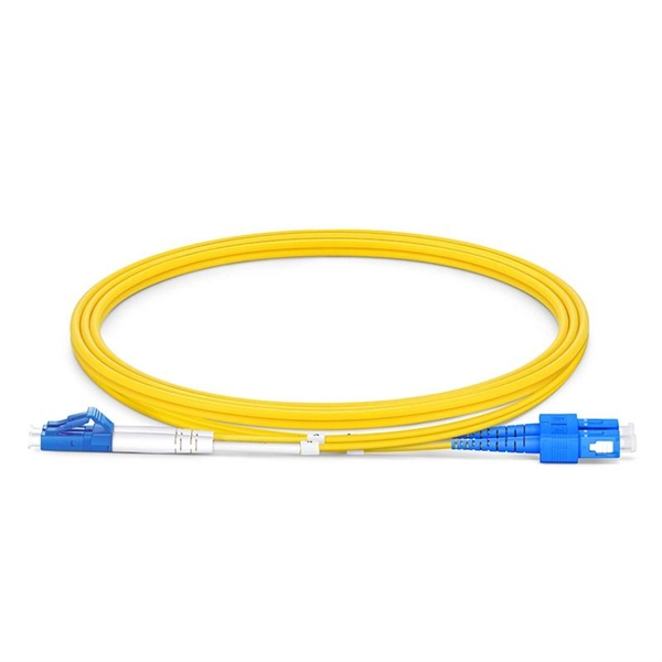
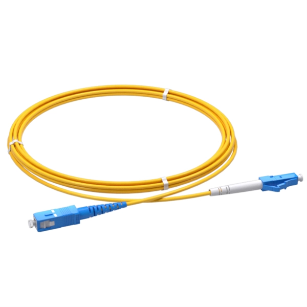
LC connectors play an integral yet often overlooked role in enabling high-speed fiber optic communications. This guide dives into the engineering behind these compact connectors, their functionality, performance metrics, and applications across modern networks. LC connectors are a ubiquitous fiber. LC connectors provide reliable and high performance connectivity in fiber optic networks. The guide covers in depth their features, types, installation techniques, troubleshooting and applications. Learn how to use LC connectors for efficient networks. As a small-form-factor (SFF) interface, LC has become the default duplex connector in enterprise LANs, telco closets, and data-center topologies because it balances density, repeatability, and cost. This guide walks. It covers LC connectors, LC patch cables, uniboot designs, armored and ultra-low-loss variants, LC adapters and patch panels, LC attenuators, MTP/MPO-to-LC cassettes, LC-interfaced transceivers, and LC media converters. It also includes practical selection guidance, real-world deployment scenarios. Fiber optic connector is a device used to connect optical fibers, capable of transmitting and receiving optical signals. There have been many types of connectors developed for fiber cable. Single mode networks have used FC or SC.
[PDF]
This article will guide you through the process of troubleshooting fiber optic connections, with a focus on ensuring proper TX and RX alignment and how to correctly switch patch cables to resolve issues. This document describes how to troubleshoot fiber optic interfaces by addressing some of the fiber optic module and cabling specifications. There are no specific requirements for this document. The information in this document is based on all Catalyst 9000 Series switches. This includes Doppler. Fiber optic networks are celebrated for their speed and reliability, but even the best systems can encounter problems. When issues like signal loss, slow speeds, or intermittent connectivity arise, systematic troubleshooting is key. 8750) Description: Internet address is. There is a single mode optical fiber cable in our datacenter going from a Cisco N5K to another N5K across different racks. The link appears to be dead and I'm hoping to fix it, but I have little to no experience with fiber. The LED light of the SFP+ ports on both switches are off (not lighting up).
[PDF]
We propose and demonstrate a fiber optic strain sensor based on a simple splice between a thin core fiber and a piece of conventional single-mode fiber. Mode dispersion generates an interference reflection s.
[PDF]