
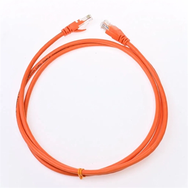
From the Security dialog box ("Setting local console switch security" on page 37), clear the Enable Screen Saver option. Click OK to save settings. To immediately deactivate the screen saver, press the Print Scrn key, and then press the Pause key. Disabling the Screen Saver mode 1. This command only works when the user is connected to a server. How do I. When I switch between sources, Windows looses the monitor and stops displaying to it. Unfortunately that seems to also black out any streams, from the likes of steam / sunshine. I believe you'd usually need EDID emulation, is there any way to have windows keep rendering when the KVM is switched to. We turn all of our screen savers off of our servers. However we noticed that if we reboot a server and do not log into it, the screen saver turns on and locks us out of our KVM switch. It simplifies the management of multiple hosts, improves work efficiency, and saves space and costs. However, when using a KVM switch, you may encounter some common issues. We will now. 1 If your console does not require a password to gain access to the Security dialog box, go to step 2. 3 Type the number of minutes for delay time (from 1 to 99) that you want to.
[PDF]
Each optical fiber, thinner than a human hair, is precisely composed of two parts: ● Core: The central channel made of ultra-pure glass or plastic. ● Cladding: Material with a lower refractive index surrounding the core. When a light signal enters the core, it doesn't travel straight. Products include phase masks, fiber optics based sensor and system, partial discharge and twin grating cavity sensors. Gould Fiber Optics is estimated to have 50-99 employees. Manufacturer of standard and custom. Contribute to apmalani/cs-178-project development by creating an account on GitHub. Wikipedia:WikiProject Core Content/Articles - Wikipedia Jump to content Main menu Main menu move to sidebarhide Main page Contents Current events Random article About Wikipedia Contact us Help Learn to edit Community portal Recent changes Upload file Special pages Search Search Appearance Donate. Fiber-optic sensors (also called optical fiber sensors) are fiber -based optical sensors for some quantity, typically temperature or mechanical strain, but sometimes also displacements, vibrations, pressure, acceleration, rotations (measured with optical gyroscopes based on the Sagnac effect), or. Are you fed up with the time and hassle of formatting text for the web? Our service lets you convert your text or document files to clean HTML instantly. Our basic service is free to use but go PRO if you need more features like converting Word or PDF documents. Check out our PRO version.
[PDF]

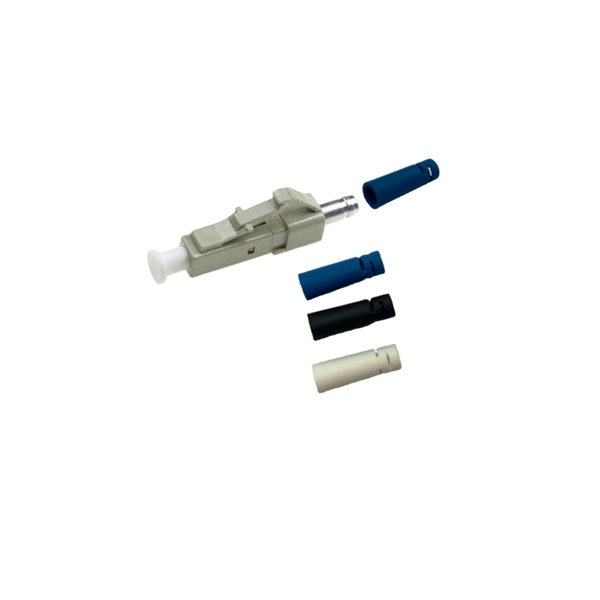
A Mode Conditioning Patch Cord (MCPC) is a specialized fiber patch cord designed to control the launch condition of light from a single-mode transmitter into a multimode fiber. Fiber optic cables primarily come in two types: Multimode Fiber (MMF): Has a larger core, allowing multiple light modes (paths) to travel. It's designed for short-distance, high-bandwidth applications within buildings or campuses. Common types are OM1, OM2, OM3, and OM4. Its primary purpose is to reduce differential mode delay (DMD) and prevent bandwidth limitation when legacy multimode. FS offers OM1 & OM2 mode conditioning fiber optic patch cables (MCP) in any connector & cable length, optimal for eliminating differential mode delay effects. This document describes the installation and use of the mode-conditioning patch cords listed in Table 1. 3z-compliant optical fiber assembly consisting of a single-mode fiber permanently coupled off-center to a 62. 5/125) fiber optic cable by offsetting the Singlemode Laser launch from the.
[PDF]

This is where a small but mighty hero comes into play: the Mode Conditioning Patch Cable (MCP). In this guide, we'll demystify what a mode conditioning patch cable is, why it's essential in specific network scenarios, and how it can save you from a world of connectivity headaches. This guide offers the key technical insights you need to select and install the optimal fiber optic cabling solutions for your specific needs. Covers the basics of fiber optic technology, including how light waves transmit data through thin strands of glass or plastic, and why fiber optics surpass. Fiber optic cables use light to transmit data, whereas traditional cables rely on electrical signals, which are more prone to interference and loss over distance. Connector types play a crucial. Fiber optic technology has transformed the way we transmit data, enabling faster, more reliable connections than traditional copper cables. Understanding fiber optic cable types is essential for anyone looking to build or maintain efficient fiber networks. We'll also. This is a plain-English guide for facilities and IT teams who want fiber that performs well, stays organized, and doesn't turn every add/change into a disruption. Start with the link's distance and speed, then pick single-mode (OS) or multimode (OM)—not the other way around.
[PDF]

In this tutorial video, we will show you step-by-step how to safely and effectively remove an optocoupler from a circuit board using desoldering wick. We will walk you through the tools you will need, the proper technique for using the desoldering wick, and the precautions to take to av. more In. Whether you're replacing a faulty component, salvaging parts from an old board, or correcting a soldering mistake, knowing how to desolder effectively is essential. This guide will walk you through the tools, techniques, and best practices for desoldering components from a circuit board safely and. Desoldering is a process that removes the solder and components from a printed circuit board or any other type of electronic assembly. This is a meticulous process and it can easily damage the board, or the components, if not properly done. Thus, it is important to know how to desolder properly. If you're desoldering a battery from a circuit board, use flush cutters to cut each wire one-at-a-time to isolate the battery before you desolder the wires. Whenever possible, create an indirect path by soldering connectors onto the battery and the circuit board. This reduces the chance of an. Sorry, an unexpected error has occurred. Why Publish? The Ultimate Guide to Desoldering: From using desoldering irons to sketchily knocking breadboard components off on the side of a table, there are tons of ways to remove components from a circuit board.
[PDF]
Key techniques include using bonding agents, saw-cutting, re-pouring concrete, mechanical connectors, and epoxy injection. Conventional methods like epoxy grout injection can address cracks effectively. Learn how to prep and bond a next-day concrete pour to repair a cold joint. This guide walks through practical surface prep, bonding methods, and timing so you can create a strong, durable joint. You'll gain actionable, plain-language steps and tips you can apply on real job sites. Identify cold. A cold joint is a common imperfection in concrete construction, occurring when fresh concrete is poured next to a section that has already begun the setting process. This discontinuity prevents the two pours from chemically integrating into a single monolithic unit, creating a weak plane within the. A cold joint in concrete is an area or surface with a structural discontinuity caused by the delayed concrete pouring between two layers of concrete. This issue compromises the structural integrity and durability of the concrete. This transition from a plastic or fluid state to a semi-solid state creates a discontinuity.
[PDF]

A ladder type cable tray tee is a fitting used to create a branch in a cable tray system, allowing cables to be routed in three directions. Its "T" shape provides a secure and efficient way to split cables from a main tray into two separate paths, ensuring organized and flexible. A cable tray tee and tee cover are components used in cable management systems to support and protect electrical and data cables. Here's a brief explanation of each:. Rigid steel cable tray tee fitting with zero tangent, safety bottom, and full accessory support. ventilation to heat producing cable such as power communication and other with the same or different width of the cable run. All fittings are available in sizes and types corresponding to the straight cable tray sections. These fitting are including: elbow, horizontal cross, vertical inside. NOTE : Equal or un equal tees can be supplied. When ordering state widths W1xW2xW3.. Office: 147/22 Nguyen Sy Sach Street, 15 Ward, Tân Binh Dist, HCMC,VN. Is it possible to connect 2 cabletrays with a "branch piece (left picture)" instead of a "tee (right picture)". The tee has 3 connectors, the branch piece only has 1 connector. I would like to ajust the "Type properties -> Fittings -> Tee" with the branch family, but can't get it accomplished.
[PDF]

In fiber-optic communication, a single-mode optical fiber, also known as fundamental- or mono-mode, is an optical fiber designed to carry only a single mode of light - the transverse mode. Modes are the possible solutions of the Helmholtz equation for waves, which is obtained by combining. Single-mode fiber is a specialized type of optical fiber designed to transmit light along a single, narrow path, or “mode. ” This technology is foundational to modern digital communication, enabling the high-speed transfer of massive amounts of data over vast distances. This type of fiber is used for transmitting signals over long distances. It is specified as the best for especially long-distance applications than multimode fiber. This saves space and money. Dual fiber modules use two fibers. They are easier to set up and give steady communication. It comprises one glass or plastic fiber and features a tiny core of about 8-10 microns in diameter. This. There are two main types of fiber optic cables: single mode and multimode. Although they can do the same job in some instances, the different construction methods make each of them better suited to certain tasks and budgets.
[PDF]