At higher altitudes, factors such as decreased air density, temperature variations, and reduced cooling efficiency can affect the electrical resistance of conductors, leading to potential power losses and reduced system performance. As electrical systems are deployed at various elevations, it becomes essential to understand the potential failures that can occur due to altitude-related factors. In this blog post, we will explore the effects of altitude on electrical equipment based on our experience Photovoltaic Research Base. As power lines are often located at varying elevations, understanding how altitude impacts conductor performance is crucial for optimizing transmission efficiency. Altitude Is A Crucial Factor That Can Significantly Impact The Performance And Reliability Of Electrical Equipment (symbol Image: CLOU) Altitude is a crucial. Heat Dissipation Challenges: Lower air density at altitude significantly reduces the effectiveness of convective cooling. Cables carrying current generate heat (I²R losses). With reduced cooling capability, cables can operate at significantly higher temperatures than at sea level, even for the. Transformers and switchgear get derated at high altitudes, but I have not seen it done for cables.
[PDF]

Optical cable lines lightning protection and strong current protection are achieved by avoiding, guiding or discharging them underground to prevent lightning and strong current from causing damage to the optical cable lines themselves, communication equipment and personnel. Since the lightning. ntly, there are a limited number of industry documents that address the requirements for optical fiber cables near high voltage circuits. One standard that has been developed by the Institute of Electrical and Electronics Enginee s, Inc (IEEE) is 1222, “IEEE Standard for All-Dielectric. The Fiber Optic Association, Inc. (FOA) was founded in 1995 to help develop the workforce to build the fiber optic networks to support a rapid expansion in communications and the Internet. ” It defines the requirements for ADSS cables placed aerially in a high. This Recommendation provides a procedure to protect the telecommunication lines using fibre optics against direct lightning discharges to the line itself or to the structures that the line enters. The protection procedure is related to the exposure of the line to direct lightning discharges and. Armored Cable: For direct burial or areas prone to crushing, use armored fiber optic cables that have an additional layer of metallic or non-metallic protective sheathing. Cable Trays and Ladders: In data centers and industrial settings, use cable trays or ladders to support runs, keeping them off.
[PDF]

Fusion splicing is the most widely used method of splicing as it provides for the lowest loss and least reflectance, as well as providing the strongest and most reliable joint between two fibers. Virtually all singlemode splices are fusion. There are two main methods of splicing: mechanical splicing and fusion splicing. This blog will delve into the nuances of each method, comparing their costs, labor efficiency, network performance, and more, to help you decide which splicing technique is best suited for your needs. Why splice? Fiber. Fusion splicing is the process of fusing or welding two fibers together usually by an electric arc. Fiber splicing means joining two optical fibers (permanently or temporarily) such that light guided in one fiber and reaching the joint (splice) can be transferred into the second fiber with low insertion loss. Another method of connecting optical fibers is termination or connectorization, which consists of processing the end of a fiber optic bundle so that it can be connected to other fibers or devices through fiber optic. Fiber Optic Cable is a form of modern network cable that has a far greater capacity than electrical communication connections. Splicing is typically required during cable installation, maintenance, or network expansion. The goal is to achieve the lowest possible optical loss (signal.
[PDF]
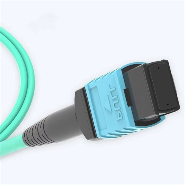
Discover the most common types and models of Direct Attach Cables (DACs), including 10G, 25G, 40G, 100G, 200G, and 400G. A Direct Attach Cable (DAC) is a factory-assembled high-speed copper cable with fixed connector “module-style” ends. It's widely used for short-reach links in data centers because it delivers low latency, simple deployment, and cost-efficient interconnects-especially for rack-level connectivity. These cables come pre-terminated with SFP (Small Form-factor Pluggable) or QSFP (Quad Small Form-factor Pluggable) connectors which simplify network setup. High-speed cable is a kind of low-cost short-distance connection solution to replace optical modules. Both of its ends have cable assemblies of a module, which are connected. Direct attach copper (DAC) cables are twinax copper assemblies with fixed transceiver-like ends. They deliver high bandwidth, low latency, and great density for top-of-rack (ToR), server-to-switch and switch-to-switch connections. This article summarizes the common DAC categories and. What is a Direct Attach Copper (DAC) Cable? Common Types And Uses Summary : Direct Attach Copper (DAC) cables provide fast, reliable, and cost-effective short-distance connections for data centers, enterprise networks, and top-of-rack setups. With passive and active variants, DAC cables offer.
[PDF]

Most modern fiber-enabled network switches require an SFP transceiver module featuring a duplex (two strand) multimode OM3 or duplex single mode OS2 connection with LC connectors. Direct attach cables with pre-terminated SFP connections may also be used. Download the. In addition, fiber cables can transmit data over several kilometers without signal degradation, making them ideal for connecting switches in large campus networks and between different buildings. As they do not emit electromagnetic signals, they're difficult to tap and secure against eavesdropping. Fiber optic cabling is increasingly used to connect network switches and other datacom equipment, especially in long-distance and mission-critical applications. Fiber provides: Increased internet signal bandwidth. The USB console port uses a USB Type A to 5-pin mini-Type B cable, shown in Figure 55 on page 85. The USB Type A-to-USB mini-Type B cable is not. Connecting a switch to a fiber optic network involves several steps and requires specific equipment to ensure a successful and efficient connection. This guide will. Many people ask the same question: Can you use a fiber optic cable with an RJ45 port? The short answer is no - RJ45 connectors are designed for electrical Ethernet signals, while fiber optics transmit light pulses through glass or plastic. However, modern networks often combine both technologies. Fiber optic technology has revolutionized data transmission, offering unparalleled speed and.
[PDF]

This standard covers the construction, mechanical, electrical, and optical performance, installation guidelines, acceptance criteria, test requirements, environmental considerations, and accessories for a nonmetallic, all-dielectric self-supporting (ADSS) fiber optic cable. An All-Dielectric Self-Supporting (ADSS) cable operates without metallic messengers, relying entirely on its aramid yarn strength members. For a typical 12-fiber ADSS cable with a 8. AFL-ADSS® (All-Dielectric Self-Supporting) cable is ideal for installation in distribution as well as transmission environments. This guide provides general recommendations for the selection of methods, equipment, and tools for the stringing of ADSS (All Dielectric Self-upporting) fiber optic cables including short and Long Span ADSS cables. The installation methods for ADSS cables are essentially the same as those used for. This Installation Manual is a recommendatory installation document provided by HANGZHOU ZION COMMUNICATION CO. The installation manual is established based on the newest issued international standards such as lEEE Std 1222: 2004, "lEEE standard for all-dielectric. Round aramid reinforced ADSS cable for intermediate and long spans, 4 – 96 fibres. VDE: A- DF 2Y (ZN) 2Y This specification covers a family of optical cables with 4 - 96 fibres for intermediate and long spans.
[PDF]
Fibre-optic Link Around the Globe (FLAG) is a 28,000-kilometre-long (17,398 ; 15,119 ) mostly- that connects the,,, and many places in between. The cable is operated by, a subsidiary of. The system runs from the eastern coast of to Japan. Its Europe–Asia segment was the fourth longest cable in the world in 2008.
[PDF]

Fiber optic cables often follow a color-coding system to indicate their type: Single-mode fibers - Typically yellow. Multi-mode fibers (OM1 & OM2) - Usually orange or sometimes gray. Choosing the right type of fiber optic cable is essential for reliable and cost-effective network performance. The two main types — Single Mode (SM) and Multimode (MM) — differ in construction, performance, and application. This guide explains how to identify them by appearance, labeling, and. When figuring out if a fiber cable is single mode, one must know the different classifications. Essentially, fiber optics are mainly categorized as: Single Mode Fiber (SMF): This type features a small core and uses laser technology to send a single light mode. Single mode fibers are used for. Knowing how to tell the difference between single mode and multimode fiber is crucial for network efficiency; the core distinction lies in the fiber's core diameter and how light travels through it, affecting bandwidth, distance, and cost. This allows for a single mode of light to travel through the core. With clear tables and updated details, it serves as a comprehensive reference for technicians handling modern fiber optic installations. We'll cover single mode, multimode, and armored fiber cables below. This small diameter core, typically around 9 microns in diameter, allows only one.
[PDF]
3 specifies performance and transmission requirements for premises optical fiber cable, connectors, connecting hardware, and patch cords. Optical fiber transition methods used to connect cabling from an array connector to simplex or duplex connectors are also. ANSI/TIA-568-C. (FOA) was founded in 1995 to help develop the workforce to build the fiber optic networks to support a rapid expansion in communications and the Internet. The charter of the FOA was to promote professionalism in fiber optics through education, certification, and. ANSI/TIA‑568. 3‑E “Optical Fiber Cabling and Components Standard” was developed by the TIA TR‑42. 11 Optical Fiber Systems Subcommittee and published in September, 2022. A full catalog of TIA specs is at org/ Learning More About Standards and Codes There are a number of ways of finding out more about cabling. This specification covers the general requirements and characteristics for cables utilizing optical fibers for signal transmission. NOTE: The base document is not DLA Land and Maritime managed and is only here as a courtesy. Please use ASSIST Quick Search to ensure you have the latest version. This. This section covers Agency requirements for fiber optic service entrance cables intended for aerial installation either by attachment to a support strand or by an integrated self-supporting arrangement, for underground application by placement in a duct, or for buried installations by trenching.
[PDF]

Fiber-optic cables are usually buried underground, which protects them from many of the issues that traditional cable or satellite internet faces. That means rain, snow, and even high winds usually won't affect your service. Wind does not directly affect a cable or fiber optic internet connection. However, high winds can indirectly disrupt internet service by damaging infrastructure like power lines and above-ground cables, leading to outages. You may also want to know: Are Bing and Yahoo the Same? · Are Sony and. High winds and flying debris can break aerial fiber lines, while ice accumulation can weigh down and snap cables. Fallen trees and other storm debris are also a common culprit in disrupting fiber network integrity. Fiber optic cables, though often encased in protective sheathing, are nonetheless. Burying fiber optic cables underground is a smart way to protect them. Underground cables stay safe from wind, rain, and cold. Workers dig deep enough and use strong pipes to keep cables safe. Underground cables do not get hit by falling. While fiber is known for its reliability, even in tough weather, there are still times when Mother Nature can disrupt your connection.
[PDF]
Whether you're installing new fiber optic cables or troubleshooting and repairing an existing fiber network, a working knowledge of the regulations that apply to your project can help you (and your team) stay s.
[PDF]

Indoor armored fiber optic cable are the latest networking infrastructure need. The cables provide ultimate mechanical protection, fire protection, and ease of installation, and thus they are suitable for indoor applications such as offices, data centers, and homes as well. These cables are suitable for both indoor and outdoor applications. Other specialized metal designs include square lock armored, spiral. In environments with high crush risk, rodents, or moisture, standard cables are not enough. What is an Armored Fiber Optic Cable? An. Supported applications include gigabit, 10 gigabit, and 40 gigabit Ethernet. Unsure Which Cables Will Suit Your Needs? What speeds and applications will this indoor armored tight-buffered plenum cable support? With bend-insensitive optical fibers (except OM1), this armored fiber optic cable is. These indoor fiber optic cables are used exclusively within buildings and must have a flame-retardant cable jacket to fit this purpose. Flame resistant cable may be deployed in-duct (conduit) or cable tray. Right selection of. Armored fiber cable is a fiber optic cable reinforced with additional protective layers to enhance its durability and resistance to external damage. These cables are designed to endure extreme environmental conditions, physical strain, and potential interference. The armor typically consists of.
[PDF]
In 1880, and his assistant created a very early precursor to fiber-optic communications, the, at Bell's newly established in. Bell considered it his most important invention. The device allowed for the of sound on a beam of light. On June 3, 1880, Bell conducted the world's first wireless transmission between two buildings, some 213 meters apart. Due to its use of an atmospher.
[PDF]

To use a power meter for fiber optic testing, always clean connectors first with lint-free wipes or click-to-clean tools. Select the correct wavelength and set your reference. You measure optical power in dBm or insertion loss in dB. Consistent procedures ensure accuracy. Verify light travels from. The most basic fiber optic measurement is optical power from the end of a fiber. This measurement is the basis for loss measurements as well as the power from a source or presented at a receiver. Typically both transmitters and receivers have receptacles for fiber optic connectors, so measuring the. An optical power meter measures the strength of light traveling through a fiber optic cable, giving you a reading in dBm (decibels relative to one milliwatt). This article will guide you through the methods, instruments, and key considerations for measuring fiber. Fiber optic cabling is the high-performance core of today's datacom networks. As network speeds and bandwidth demands increase, fiber performance requirements have become more stringent. Fiber testing is more important than ever. An OPM uses a photodiode to generate an electrical current proportional to optical power.
[PDF]
The digital optical audio cable by AmazonBasics is among the best there is in the market. I highly recommend this product to everyone looking for a dependable Toslink cable. You can conveniently connect an.
[PDF]