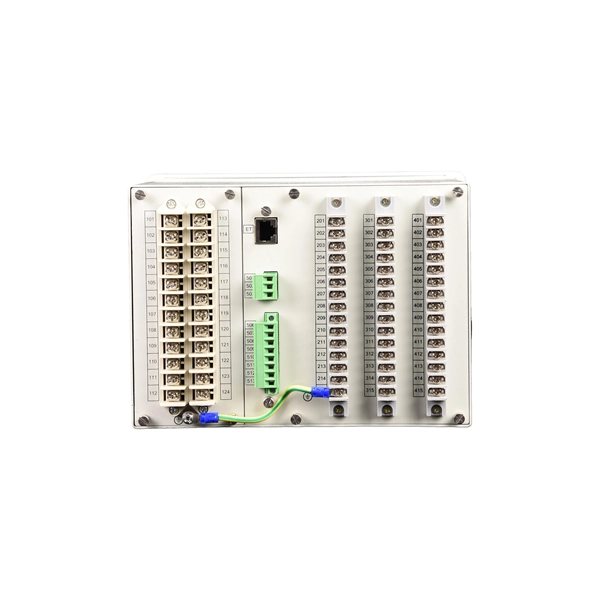
In an Ethernet patch panel diagram, each port on the patch panel is represented by a numbered or labeled square or circle. The diagram typically includes details such as the port numbers, cable types, and the devices connected to each port. Ethernet patch panel diagram is a visual representation of the connections between Ethernet cables and network devices, such as switches and routers. It provides a clear overview of how the network is structured, allowing network administrators to easily troubleshoot and manage the network. This information can be used to track the location of devices, their serial numbers, and their IP addresses. Change Management: Patch panel connection diagrams can be used to track. A patch panel is an essential component in a network system that provides a central location for connecting multiple devices or cables. The patch panel serves as. A pair of managed Gigabit Ethernet rack-mount switches, connected to the Ethernet ports on a few Panduit patch panels using Category 6 patch cables. (All equipment is installed in a standard 19-inch rack. Each port has a patch connection that links it to another port in another part of your building.
[PDF]

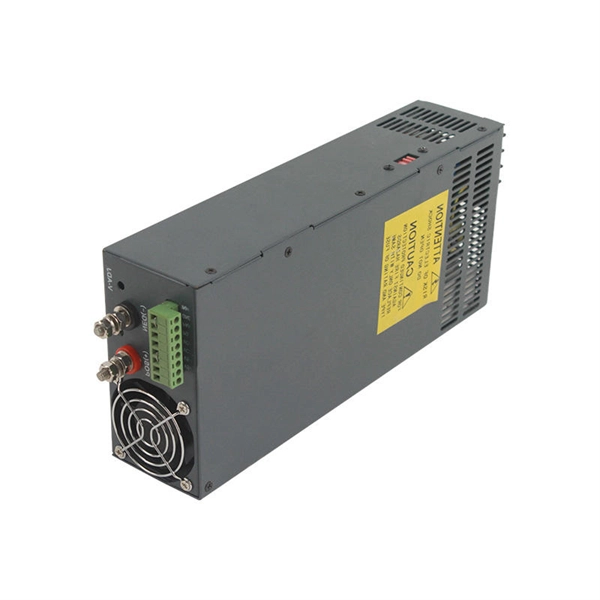
【Terminal Versatility】- Each 12V marine busbar features 5 x M6 (1/4”) stainless steel terminal studs for positive and negative connections, ensuring secure and efficient power distribution. Check each product page for other buying options. Price and other details may vary based on product size and color. Need help?. These bars are tin-plated copper and have stainless steel terminals. Also known as bus bars, they serve as connection points between wires with ring or spade terminals. The underside is sealed, so the bars can be safely mounted to conductive surfaces. Distribution Bar Covers— Distribution bar. Our automotive busbars and terminal blocks allow you to consolidate wiring and distribute electrical power in a cost-effective manner. So, what's the difference? A busbar. Pricing (USD) Filter the results in the table by unit price based on your quantity. Busbar Barrier Terminal Blocks are available at Mouser Electronics. Mouser offers inventory, pricing, & datasheets for Busbar Barrier Terminal Blocks. Pick compact mini bus bars, high amp PowerBar and MaxiBus models, and 4 to 20 circuit terminal blocks with covers for clean marine, vehicle, RV, and bench wiring. Shop terminal blocks, barrier strips, and DC bus bars.
[PDF]
In conventional network construction, we divide the switches into a hierarchical structure according to the number of connected network devices. Typically, we have three structural levels: access, aggregation, and core. An aggregation switch is a network device that consolidates traffic from multiple access switches, wireless access points, or other edge devices and forwards it to core switches or routers. By bundling multiple network connections into a single high-bandwidth link, aggregation switches help. Whether in enterprise networks, data centers, or campus environments, aggregation switches act as a bridge between access switches and core switches. It is essential for larger networks requiring efficient data flow. You may also. Due to all traffic in a system is transmitted to the core switch, it is required to have high reliability, high efficiency, manageability, and low latency. Generally, it adopts the managed switches in the core layer. The core layer is an integral part in networking, but it is not requested in all. Switch aggregation, also known as link aggregation or trunking, is a method used in computer networking to combine (aggregate) multiple network connections in parallel. This arrangement increases throughput beyond what a single relationship could sustain, offers redundancy in case one of the links.
[PDF]
Electric power distribution systems are designed to serve their customers with reliable and high-quality power. The most common distribution system consists of simple radial circuits (feeders) that can be ove.
[PDF]

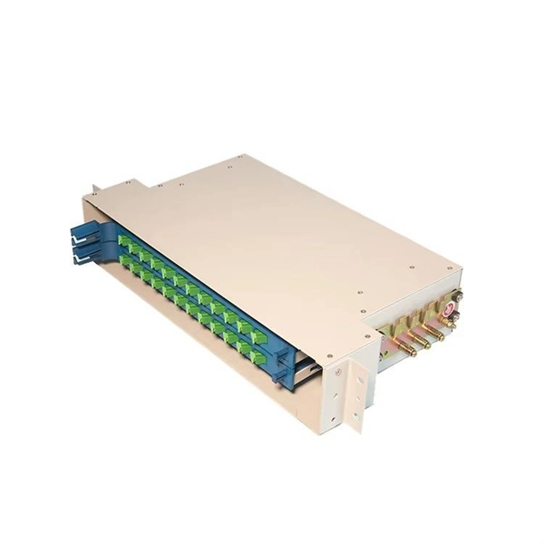
An Optical Splitter, also known as a beam splitter, is a passive optical device that divides a single input optical signal into two or more output signals. Conversely, it can also combine multiple signals into one. Knowing the difference between a splitter and an optical coupler helps you build better networks. You make your network work better when you pick the right device for each job. You can connect many users to one port with 1:n or 2:n splitters. By dividing a single optical signal from a central Optical Line Terminal (OLT) into multiple outputs for Optical Network Terminals (ONTs) at users' homes, splitters eliminate the need for dedicated fibers to each residence—slashing infrastructure costs while scaling network reach. This guide. In a Passive Optical Network (PON), a single optical fiber carries massive amounts of data using light. Signal Input: The fiber splitter receives the optical signal from the upstream network node and enters the splitter through the input fiber. Signal Distribution: Inside the splitter, according to the design structure and different. Splitters are passive optical devices that divide or combine optical signals, and they come in various types, including power splitters, uneven splitters, and wavelength-division multiplexing (WDM) splitters. Each type serves specific applications, enabling efficient use of optical infrastructure.
[PDF]

When you look at a fiber optic cable, the outer jacket color instantly tells you what type of fiber is inside. This color-coding system is standardized under TIA-598-C, making it easier for technicians and installers to identify cables at a glance. By adopting the TIA/EIA‑598C standard, you gain a universal “language” of colors that speeds identification, reduces miswiring, and enhances safety across cable jackets, connectors, buffer tubes, and splice trays. Error Reduction: A standardized palette prevents costly mis‑splices and. In fiber communications, the color of the fiber is not only an eyes-only indicator—it is actually used for determining the quantity, type of the fiber, and use of the fiber. Every fiber is color-coded, and this is a very crucial detail in the installation process, maintenance procedure, and. The fiber optic color codes refer to a standardized system used to identify individual fibers within a particular cable. These codes ensure correct organization and connectivity during installation or maintenance processes. The colors typically follow a color scheme established by industry. To solve this, the industry relies on an authoritative color-coding system: the EIA/TIA-598 Standard, which provides unified guidelines for identifying optical fibers, cable jackets, buffer tubes, and connectors.
[PDF]

The most commonly used primary distribution voltages are 11 kV, 6. Utilities may have some control over and access to the energy stored in electric vehicles attached to the grid. The voltage used for primary distribution depends upon the amount of power to be conveyed and the distance of the substation required to be fed. Due to economic considerations, primary distribution is carried out by. There are five main functions of the distribution substation: Voltage transformation: One or more transformers will always be located within the substation to step down the voltage to the primary distribution voltage level. These transformers will always be three-phase banks, or they will be three. Electric power distribution is the final stage in the delivery of electricity. Electricity is carried from the transmission system to individual consumers. These taps are typically single phase, but may also be two phases or three phases. Laterals can be directly connected to main trunks, but are more commonly protected by protective devices such as fuses. distribution voltages are between 4 and 35 kV. In this article, unless otherwise specified, voltages are given as line-to-line voltages; this follows normal industry practice, but it is sometimes a source of confusion. A voltage class is a.
[PDF]