A beam splitter or beamsplitter is an that splits a beam of into a transmitted and a reflected beam. It is a crucial part of many optical experimental and measurement systems, such as, also finding widespread application in.
[PDF]

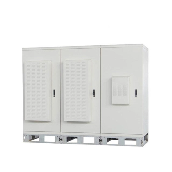
In modern FTTH architectures, the ODN is the physical fiber layer that distributes optical signals from the central office to end users. Operators consider ODN design as one of the most important factors affecting: Network coverage Optical loss performance Deployment cost. This passive layer is known as the Optical Distribution Network (ODN). Its role is to provide an optical transmission channel between the OLT and the ONU. The ODN network design is a physical facility that connects the communication room and user equipment, and is a key component. Short summary: The Optical Distribution Network (ODN) is the passive infrastructure linking the central office to the subscriber in FTTH. This guide delves into essential ODN components like splitters, distribution boxes, and ODFs, showcasing how Hainan ZTO Cable Co. It's the silent, robust highway that delivers blazing-fast Fiber-to-the-Home (FTTH) and 5G services. The maximum permissible optical power attenuation between OLT optical ports to ONT input is 28dB, which is by utilizing the so-called Class B optical network. At the heart of every Fiber-to-the-Home (FTTH) deployment lies the Optical Distribution Network (ODN) — a meticulously engineered passive infrastructure that enables operators to deliver massive bandwidth, low latency, and reliable service to millions of users. The ODN connects the Optical Line.
[PDF]
To set up your router for fiber internet quickly, connect the router to your fiber modem, access the router's settings via a web browser, and input the provided ISP credentials. Make sure to update the firmware, configure Wi-Fi security, and customize your network name for. Q: How do I install my broadband modem and set up my Internet connection? Installing your broadband modem and setting up your Internet connection involves several steps. First, you need to physically connect your modem to your computer using an Ethernet cable or wirelessly through a router. Next. This wikiHow guide will walk you through setting up a Wi-Fi connection in Windows XP and connecting to the internet. We'll also cover the risks so you know what you're getting into. Check for or install a wireless adapter. Enable Wireless Zero Configuration. Right-click the network icon. Why Use Fiber Optic Internet? Before diving into the setup, let's quickly. Setting up a home network on Windows XP can seem like a daunting task for beginners, but with the right guidance, it becomes a straightforward and rewarding endeavor. This beginner's guide is designed to walk you through the easy steps necessary to establish a functional network within your own. This article provides a detailed guide for establishing internet connectivity in Windows XP via dial-up modem, Ethernet, and Wireless connections, including troubleshooting common issues.
[PDF]

They are the bridge between fiber optic cables in the field and the equipment or patch panels that manage them. By combining factory-installed connectors with spliced bare fiber, pigtails ensure that network installers can create fast, reliable, and cost-effective terminations. Pigtail connections are most frequently used to ground a switch or electrical outlet and for electrical devices that need to connect to multiple circuit wires. A pigtail is composed of three strands of wire. We'll guide you through the fundamentals of creating secure links between multiple conductors and terminals. Pigtails act as bridges, allowing you to connect several wires to a single point without overloading connections. Professionals often prefer this method because it isolates issues. Fiber pigtails are simple in appearance, yet essential in function. It ensures a secure connection by combining wires with a wire connector, like a twist-on connector or a wire nut, and then linking them to the intended terminal or fixture. Pigtails serve. A pigtail wire is a short cable used to lengthen short wires. This pigtail technique is applicable in several home and automotive wiring projects, especially for circuit grounding wires. The National Electrical.
[PDF]

In this tutorial, I will show you how you can connect the Optocoupler to Arduino, read the data as Analog or Digital, and if necessary convert the analog values to digital, and how to reduce noise from the sensor. The Infrared Slotted Optical Optocoupler Module is a device that uses infrared light to transmit signals between two electrically isolated circuits. It consists of an infrared emitter (LED) and a photodetector (phototransistor) housed in a slotted enclosure. When an object passes through the slot. Slotted Optocouplers (Photo Interrupters) are very useful sensors, often included in Arduino projects to detect position of moving objects, measure speed of rotation, or linear motion, frequency of events, and many others. They are easy to use, but it is important to understand how they work, so. This tutorial is a comprehensive, practical guide to the Speed Sensor / Tacho Sensor (Slot-Type Optocoupler) (Leobot Product #245). Moreover, a simple application is programmed that shows how to wire and how to program an Arduino when working with the module. In this tutorial, the module is used as an “digital input board”. If you want to use the. In this project, I will talk about Phototransistor Optical Interrupter Switches (Opto Coupler) Module, how this module works and helps in determining the speed of a rotating object and finally I will show you how to Interface Optical Interrupter Switch Sensor with Arduino and measure the speed of a.
[PDF]
The 3R A3140 AA serves as a fully compatible, drop-in replacement for the HCPL-3140, featuring matched performance metrics including propagation delay, CMTI, and output current, ensuring dependable real-world implementation in industrial and automation settings. The HCPL-3140/HCPL-0314 family of gate driver optocouplers consists of an GaAsP LED optically coupled to an integrated circuit with a power output stage. These optocouplers are ideally suited for driving power IGBTs and MOSFETs used in motor control inverter applications. The high operating voltage range of the. 0. Here you can find various types and values of electronic parts from the world's leading manufacturers. The HCPL-3140/A3140 components of Jotrin Electronics are carefully chosen, undergo stringent. The HCPL-3140-000E is a 0.
[PDF]
Answer: The current transfer ratio (CTR) is an important parameter in optocoupler selection. The gain of an optocoupler is expressed as the Current Transfer Ratio (CTR). It is defined as the ratio of the phototransistor output current (Ic) to the LED input current (If), expressed as. The current transfer ratio is a parameter similar to the DC current amplification ratio of a transistor (h FE) and is expressed as a percentage indicating the ratio of the output current (I C) to the input current (I F). The CTR has the following characteristics and is therefore as important as the. An optocoupler, also known as photocoupler or opto-isolator, is a device which can transfer an electrical signal across two galvanically-isolated circuits by way of optical coupling. Transferring signals over a light. As I understand the optocoupler current transfer ratio, CTR is like the hfe of a transistor. I can't understand if the CTR is or isn't a critical value and for what applications is it used in. Optocouplers contain both a light-emitting diode (LED) and a photo detector. The current transfer ratio. The current transfer ratio (CTR) refers to the ratio of the collector current at the output side I c to the input current passed to the LED at the input side I F expressed as a percentage. It is defined by the following formula.
[PDF]

An Optical Splitter, also known as a beam splitter, is a passive optical device that divides a single input optical signal into two or more output signals. Conversely, it can also combine multiple signals into one. Knowing the difference between a splitter and an optical coupler helps you build better networks. You make your network work better when you pick the right device for each job. You can connect many users to one port with 1:n or 2:n splitters. By dividing a single optical signal from a central Optical Line Terminal (OLT) into multiple outputs for Optical Network Terminals (ONTs) at users' homes, splitters eliminate the need for dedicated fibers to each residence—slashing infrastructure costs while scaling network reach. This guide. In a Passive Optical Network (PON), a single optical fiber carries massive amounts of data using light. Signal Input: The fiber splitter receives the optical signal from the upstream network node and enters the splitter through the input fiber. Signal Distribution: Inside the splitter, according to the design structure and different. Splitters are passive optical devices that divide or combine optical signals, and they come in various types, including power splitters, uneven splitters, and wavelength-division multiplexing (WDM) splitters. Each type serves specific applications, enabling efficient use of optical infrastructure.
[PDF]

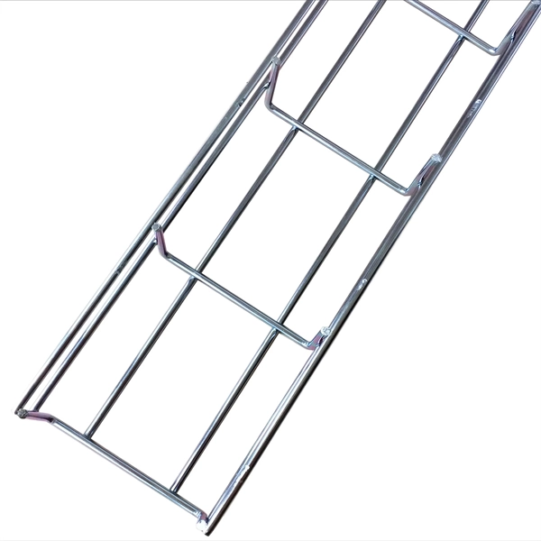
A ladder type cable tray tee is a fitting used to create a branch in a cable tray system, allowing cables to be routed in three directions. Its "T" shape provides a secure and efficient way to split cables from a main tray into two separate paths, ensuring organized and flexible. A cable tray tee and tee cover are components used in cable management systems to support and protect electrical and data cables. Here's a brief explanation of each:. Rigid steel cable tray tee fitting with zero tangent, safety bottom, and full accessory support. ventilation to heat producing cable such as power communication and other with the same or different width of the cable run. All fittings are available in sizes and types corresponding to the straight cable tray sections. These fitting are including: elbow, horizontal cross, vertical inside. NOTE : Equal or un equal tees can be supplied. When ordering state widths W1xW2xW3.. Office: 147/22 Nguyen Sy Sach Street, 15 Ward, Tân Binh Dist, HCMC,VN. Is it possible to connect 2 cabletrays with a "branch piece (left picture)" instead of a "tee (right picture)". The tee has 3 connectors, the branch piece only has 1 connector. I would like to ajust the "Type properties -> Fittings -> Tee" with the branch family, but can't get it accomplished.
[PDF]
Optical amplifiers work differently. They amplify the light directly, with no conversions. This process is faster, more efficient, and keeps the signal clearer. Using optical amplifiers helps reduce signal distortion, lowers system costs, and supports long-distance communication. The most common types include: Erbium Doped Fiber Amplifiers (EDFA): EDFAs are the most commonly used type of optical amplifier in telecommunications. They play a vital role in modern optical communication systems, enabling the transmission of high-speed data over long-haul networks. An optical amplifier is a device that boosts the strength of an optical signal. 2dB per kilometer for 1. This means that over a distance of 100km, a signal can lose around 20dB. This principle dictates that a photon can interact with an atom already in an excited energy state, forcing the excited atom to immediately release its stored energy as a second photon. It does this without changing the light into an electrical signal. In the past, systems used repeaters to fix weak signals. These repeaters turned light into electricity, boosted the signal, and then. The SPIE Digital Library offers a comprehensive range of content on optical amplifiers, reflecting their significance in modern photonics and telecommunications. The library includes a variety of peer-reviewed papers, conference proceedings, and technical articles that delve into the fundamental.
[PDF]
The noise performance of an erbium-doped fiber amplifier (EDFA) is characterized by modeling optical amplifiers as four-level or three-level systems. The gain and noise performance are then examined under forward and reverse pumping. A polynomial regression model using Generalized Least Squares (GLS) is proposed for real-time noise figure estimation in Erbium-Doped Fiber Amplifiers (EDFAs), achieving accuracy within the measurement uncertainty of optical spectrum analyzers. In this paper, a simulation of an EDFA has been studied to. Noise characteristics of erbium-doped fiber amplifier pumped at 980 nm. 4dB was measured for pump powers of on y 5. 8mw, cons multiplexed video transmission systems4 operating in the 1. This content is available for download via your institution's subscription. To access this. paper and electronic copies of this thesis and grant others the right to do o. Figure 1: Layout of the system considered in the analysis of gain and ASE The characteristics of noise and gain.
[PDF]

This guide will walk you through the process of checking photo sensors using a multimeter, covering various types of photo sensors, the necessary tools and safety precautions, and the specific measurement techniques involved. Knowing how to effectively use a multimeter to test photo sensors can save you time, money, and frustration when dealing with malfunctioning devices. more What is a Voltage Divider? | What is a Voltage. Before replacing the sensor or fixture, it's efficient testing it first, With a few tools and a step-by-step process you can find whether your outdoor lighting control system is working as intended or if the problem lies elsewhere. In this complete guide from Lead-Top, a global leader in photocell. In this blog post, we explain step-by-step how to troubleshoot a sensor with a digital multimeter (DMM). Here are the steps: Troubleshooting a sensor measurement failure requires mechanical tools to uncover the protective shields or components so you can reach the sensor in question. Always follow the manufacturer's instructions for the sensor and multimeter. Ensure the sensor is properly connected to the multimeter and. A multimeter is an indispensable diagnostic tool for anyone working with electronics, electrical systems, or indeed, sensors. It's a versatile device capable of measuring voltage, current, and resistance, providing crucial insights into the health and functionality of electrical circuits and.
[PDF]
Connecting fiber optic cable directly to a standard Ethernet port is not possible. Ethernet ports are designed for copper cables (like Cat5e or Cat6), which transmit data using electrical signals. The process to connect fiber optic cable to router requires careful attention to detail, but I'll walk you through every critical step with the precision and clarity you deserve. This comprehensive guide combines industry standards with field-tested practices to ensure you achieve a rock-solid. In this guide, we'll walk you through how to connect a fiber optic cable to a router safely and efficiently. Why Use Fiber Optic Internet? Before diving into the setup, let's quickly recap why fiber optics are worth the effort: Lightning-fast speeds (up to 1 Gbps or higher). Here's a step-by-step guide to help you through it. Check compatibility: Before you begin, make sure your router supports fiber optic connection. Not all routers can connect directly to a fiber cable, so it is important to verify this information before continuing. Gather. Unlike regular electrical wires, these glass fibers can snap or bend too far. Proper connectors, clean ends, and a good splice keep everything sharp and stable. When you connect the fiber optic cable correctly, you keep your fiber internet, ONT (optical network terminal), and router running at peak. Connecting a fiber optic cable to a router involves a few key steps and specialized equipment.
[PDF]