They support link aggregation protocols such as Link Aggregation Control Protocol (LACP) and Static Link Aggregation, which allow multiple physical links to be combined into a single logical connection. This enhances bandwidth, redundancy, and ensures failover capability in case of a. The three layers of a traditional three-layer network design are the core layer, aggregation layer, and access layer. Together, these layers can offer consumers a network that is safe, reliable, and affordable. As the physical part of the aggregation layer, aggregation switches typically play a. An aggregate switch is a high-capacity network switch that consolidates connections from multiple access switches, acting as a central point for managing network traffic and providing enhanced bandwidth capabilities. It is essential for larger networks requiring efficient data flow. This article looks at what each such tool does, compares how they differ from each other, and offers suggestions as to what sort of network each. The aggregation (sometimes also called distribution) layer is a real crossroad. Its primary goal is to increase network scalability by providing a single place to interconnect multiple access switches and the core layer.
[PDF]
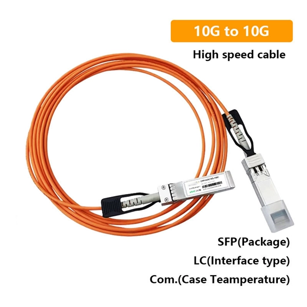
Below are eight SFP-based choices commonly used in tunnel monitoring, traffic analytics, and roadside IP cameras. Each item includes the key specs that matter in the field, a best-fit scenario with realistic numbers, and quick pros and cons. GigaVUE ® TA Series, part of the Gigamon Deep Observability Pipeline, aggregates traffic from SPAN/TAPs to deliver pervasive edge visibility. Supporting speeds from 1G to 400G, it improves monitoring efficiency and reduces costs through core intelligence and GigaVUE-OS. The GigaVUE TA Series is. An Aggregation or "Top-of-Rack" switch is designed to connect everything in a rack at high speeds, then have an even bigger pipe out to the rest of the network. The Pro Aggregation does this with it's SFP28 25Gbps ports. The regular Aggregation switch is best used to connect all devices in a rack. What Is an Aggregation Switch? An aggregation switch is a network device that consolidates traffic from multiple access switches, wireless access points, or other edge devices and forwards it to core switches or routers. By bundling multiple network connections into a single high-bandwidth link. We'll be happy to answer all of your technical, pricing & availibility questions. Road monitoring deployments live or die by link stability: vibration, temperature swings, moisture, and long fiber runs can turn a “works on the bench” SFP into a field failure.
[PDF]

It can be seen from the above that the aggregation switch has functions such as source address, destination address filtering, real-time policy, security, network isolation, and segmentation. Compared with access switches, aggregation switches have better performance and higher. What is an Aggregation Switch and How Does it Work? An aggregation switch consolidates data traffic from multiple network access switches into a single high-bandwidth link directed toward a core network or data center. The primary function of an aggregation switch is to aggregate and forward data. A fiber optic aggregation switch is a high-capacity network device designed to integrate and manage multiple fiber optic connections from access layer switches into fewer and faster uplink connections to the core network. It is essential for larger networks requiring efficient data flow. You may also. All-optical Ethernet switches are a type of switch that provides optical uplink and downlink ports, making them an ideal choice for building an all-optical campus network. They can function as core, aggregation, and access devices on campus networks and connect to upstream and downstream devices. As the physical entity of the aggregation layer, the aggregation switch's primary function is to aggregate the data of the access layer switch and forward it to the core switch to reduce the burden on the core layer. Cisco's aggregation switch What is the Role of the Aggregation Switch in the.
[PDF]
In conventional network construction, we divide the switches into a hierarchical structure according to the number of connected network devices. Typically, we have three structural levels: access, aggregation, and core. An aggregation switch is a network device that consolidates traffic from multiple access switches, wireless access points, or other edge devices and forwards it to core switches or routers. By bundling multiple network connections into a single high-bandwidth link, aggregation switches help. Whether in enterprise networks, data centers, or campus environments, aggregation switches act as a bridge between access switches and core switches. It is essential for larger networks requiring efficient data flow. You may also. Due to all traffic in a system is transmitted to the core switch, it is required to have high reliability, high efficiency, manageability, and low latency. Generally, it adopts the managed switches in the core layer. The core layer is an integral part in networking, but it is not requested in all. Switch aggregation, also known as link aggregation or trunking, is a method used in computer networking to combine (aggregate) multiple network connections in parallel. This arrangement increases throughput beyond what a single relationship could sustain, offers redundancy in case one of the links.
[PDF]
The Huawei S5731-S24T4X is a switch from Huawei's S5731 series, designed for enterprise networks. It is a versatile and high-performance device that supports a range of applications, including data center, campus, and branch networking. The Xingmai Passive Ethernet Network (PEN) is an all-optical campus network solution based on the passive technology. Leveraging mainstream Ethernet protocols, the Xingmai PEN solution uses optical fibers to implement passive data transmission without the need of any ELV room. 24 Gigabit Ethernet Ports: Provides 24 10/100/1000 Mbps. Demand for Wi‑Fi 6-ready campus networks is growing rapidly, the Huawei S5732 Series empowers modern networks as a cutting-edge Aggregation Switch and Campus Switch, offering multi-Gigabit access, PoE++, and service intelligence. Its capabilities—from built-in WLAN AC to VXLAN and MACsec—ensure. CloudEngine S6780-H series switches are Huawei's next-generation enterprise-class core and aggregation switches that provide 64 x 100GE/32 x 25GE ports and 16 x 400GE optical ports. CloudEngine S5732-H hybrid optical-electrical.
[PDF]
Switches in this layer are called access switches. In other words, an access switch forwards traffic between connected devices and the rest of the LAN. The following image shows a network that contains. The access layer is where endpoints (such as phones, laptops, video-conferencing sets, printers, IoT sensors, IP cameras, and servers) are primarily connecting to the network. FortiSwitch units distribute the ports to plugs. Access layer switches are primarily deployed in Layer 2 mode in the data center. A Layer 2 access topology provides the following unique capabilities required in the data center: VLAN extension—The Layer 2 access topology provides the flexibility to extend VLANs between switches that are connected. It contains three layers: core, distribution, and access. The core layer is the backbone of the network. It provides a high-speed connection between different distribution layer devices. The layer 2 switches collect the data from core switches, identify the type of data packet and the address of the access device. Further, the data packets are forwarded to the addressed group of.
[PDF]

Normal WDM (sometimes called BWDM) uses the two normal wavelengths 1310 and 1550 nm on one fiber. Coarse WDM provides up to 16 channels across multiple transmission windows of silica fibers. Dense WDM (DWDM) uses the C-Band (1530 nm-1565 nm) transmission window but with denser. In fiber-optic communications, wavelength-division multiplexing (WDM) is a technology which multiplexes a number of optical carrier signals onto a single optical fiber by using different wavelengths (i., colors) of laser light. This guide delves into the principles, types, applications, and future trends of WDM. The concept involves sending multiple independent data streams down a single strand of fiber, much like transforming a single-lane road into a. Abstract Wavelength division multiplexing or WDM allows the combining of a number of independent information-carrying wavelengths onto the same fiber, because of the wide spectral region in which optical signals can be transmitted efficiently. This chapter addresses the operating principles of WDM. 📦 For purchasing, use the RP Photonics Buyer's Guide for wavelength division multiplexing. It provides an expert-curated supplier directory, buyer-focused technical background information, and structured selection criteria to support professional procurement decisions. WDM allows communication in both the directions in the fiber cable. In WDM, the optical signals from different.
[PDF]
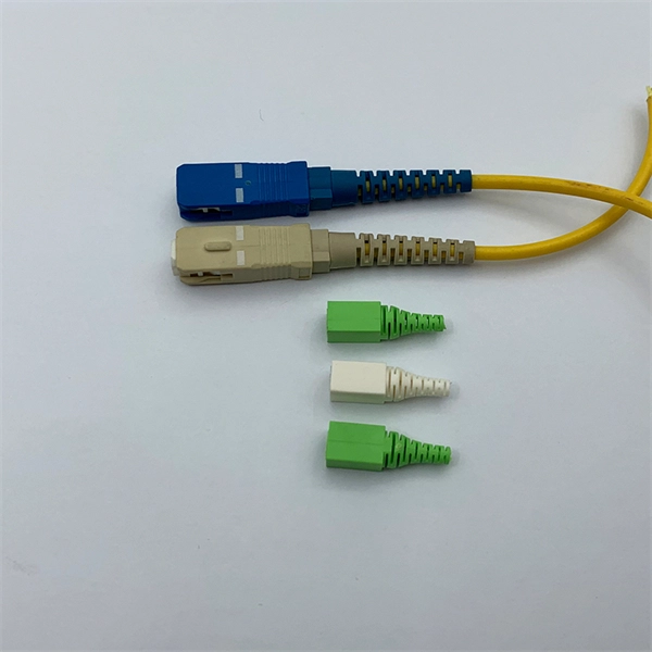
Pigtail, also known as pigtail, has only one end with a connector, and the other end is a broken end of a fiber optic cable core. It often appears in fiber optic terminal boxes. (couplers, jumpers, etc. are also used between. Long tail fibers consist of a phage-proximal and a phage-distal rod, each around 80 nm long and attached to each other at a slight angle. The phage-proximal rod is formed by a homo-trimer of gene product 34 (gp34) and is attached to the phage-distal rod by a monomer of gp35. are also used between them). One. The tailed phage T4 encodes a specialized device for this purpose, the long tail fiber (LTF), which allows the virus to move on the bacterial surface and find a suitable site for infection. Consequently, the infection efficiency of phage T4 is one of the highest, reaching the theoretical value of. Bacteriophages, often called phages, are viruses that infect and replicate within bacteria. These tiny biological entities play a significant role in microbial ecosystems. Tail fibers are structures on the phage that mediate their initial interaction with bacterial hosts, allowing them to recognize. The tail (Fig. Infection is initiated with the reversible attachment of six long tail fibers (LTFs) to the cell's outer layer of lipopolysaccharides, followed by transformation of the.
[PDF]
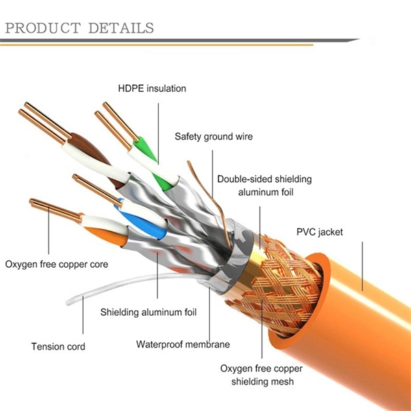
The protective outer layer, often called the jacket, surrounds the entire fiber optic cable. This layer is typically made from durable materials such as plastic, designed to protect the fragile core and cladding from external damage. Different types of cable are used for fiber-optic communication in different applications, for example long-distance. A fiber optic cable consists of five basic components: the core, the cladding, the coating, the strengthening fibers, and the cable jacket. When searching for a fiber optic cable, we need to pay attention not only to the connectors, such as SC to ST fiber cable, LC to SC fiber patch cable, or SC to. Fiber optic cables are made primarily of ultra-pure glass, specifically silicon dioxide (silica), the same compound found in quartz and ordinary sand. Each fiber is thinner than a human hair, yet it carries data as pulses of light across enormous distances. The materials are chosen for their clarity, flexibility, strength, and durability. What is Optical Fiber? Optical fiber consists of flexible glass or plastic strands engineered to transmit light. Manufacturers produce these fibers through a.
[PDF]
The layer 2 switches prevent over-crowding of data packets in transmission links and access devices. · Layer Positioning: The data link layer (Layer 2) of the OSI model, realizing local forwarding of data frames based on MAC addresses. · Core Task: Establishing direct interconnections between devices within a local area network to ensure efficient communication within the same network segment. ·. The core layer is the backbone of the network. It provides a high-speed connection between different distribution layer devices. The distribution layer connects the access layer to the core layer. When designing a campus LAN, you may. In enterprise networking, the hierarchical three-tier model is divided into three distinct roles: access switches (which connect end-user devices to the network via Layer 2), distribution switches (which route inter-VLAN traffic and enforce security policies at Layer 3), and core switches (which. The core switch is the most important piece of hardware in this infrastructure, acting as the high-speed, central nervous system that ensures all parts of the network can communicate. The core switch functions as the central point of the entire network, forming the high-speed backbone for the. Distribution Layer: The distribution layer is an intermediate layer. Simply put, it's the kingpin that keeps your network humming. You may also want to know: Can a Nintendo Switch Play DS Games? ·.
[PDF]

In this article, I'm going to describe how to set up Link Aggregation between two managed switches to provide connectivity, redundancy, and expanded bandwidth. Managed switches provide many advantages for a growing network, including support for VLANs, QoS, and Trunking. I touched on simple VLAN configuration a while back. in the United States and in other countries. App Store and the Apple logo are trademarks of Apple Inc., registered in the U. Google Play and the Google Play. Link Aggregation in UniFi allows you to combine two or more ethernet ports into one. The NVR is connect via Fibre to the USW as well. So. ? Any hints welcome! Archived post. New comments cannot be posted and votes cannot be cast. Imagine transforming multiple network cables into one giant, super-speed "data highway. " That's exactly what link aggregation does. It combines multiple Ethernet connections into a single logical connection, boosting speed, enhancing. Thank you for purchasing the Ubiquiti Networks® EdgeSwitch® XG. This Quick Start Guide is designed to guide you through installation and also includes warranty terms. TERMS OF USE: All Ethernet cabling runs must use CAT6A (or above). It is the professional installer's responsibility to follow local.
[PDF]
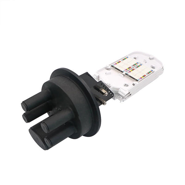
Backbone cable connects telecommunications spaces through dedicated infrastructure pathways, serving as the primary network connection between entrance facilities, equipment rooms, and telecommunications rooms. Structured cabling is an infrastructure that arranges the wires and cables of a building in an organized and modular way. In contrast to traditional point-to-point layouts, a structured cable setup clearly defines wiring standards. A structured cabling system is composed of six subsections, each. As data center environments scale in density and complexity, system integrators must make critical decisions about fiber architecture. Choosing between MPO and LC (Lucent Connector) fiber impacts compatibility, scalability, and deployment efficiency. Understanding how each solution fits within a. This Section defines the general design requirements for a uniform Intra and Inter-Building Communications Optical Fiber Backbone Cabling Infrastructure that shall be followed for all OFCC Technology construction projects. All equipment shall be UL listed. All equipment and Installation Practices. Fiber aggregation is a common technique used in fiber optic networks to improve the infrastructure and increase network capacity. So, what exactly are fiber aggregation points? They are the centralized hubs where multiple fiber optic cables intersect. My extensive experience shows that backbone cabling consists of fiber optic cables or.
[PDF]

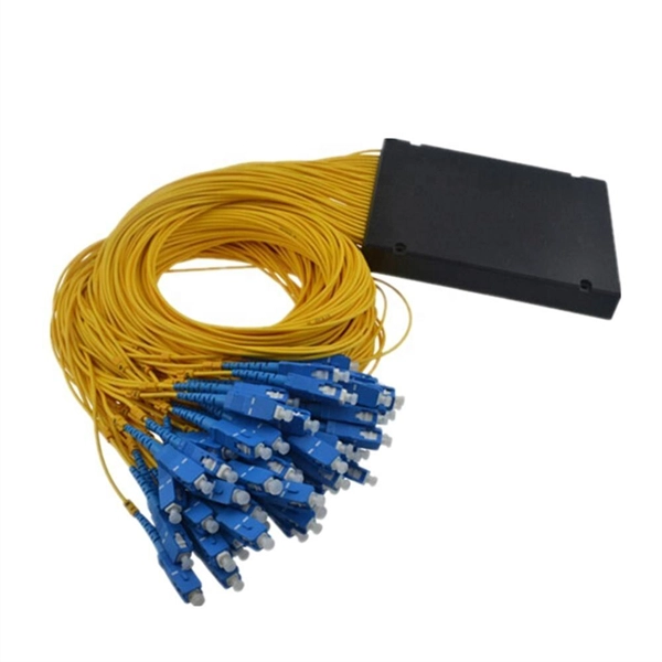
An Optical Splitter, also known as a beam splitter, is a passive optical device that divides a single input optical signal into two or more output signals. Conversely, it can also combine multiple signals into one. Knowing the difference between a splitter and an optical coupler helps you build better networks. You make your network work better when you pick the right device for each job. You can connect many users to one port with 1:n or 2:n splitters. By dividing a single optical signal from a central Optical Line Terminal (OLT) into multiple outputs for Optical Network Terminals (ONTs) at users' homes, splitters eliminate the need for dedicated fibers to each residence—slashing infrastructure costs while scaling network reach. This guide. In a Passive Optical Network (PON), a single optical fiber carries massive amounts of data using light. Signal Input: The fiber splitter receives the optical signal from the upstream network node and enters the splitter through the input fiber. Signal Distribution: Inside the splitter, according to the design structure and different. Splitters are passive optical devices that divide or combine optical signals, and they come in various types, including power splitters, uneven splitters, and wavelength-division multiplexing (WDM) splitters. Each type serves specific applications, enabling efficient use of optical infrastructure.
[PDF]

Cable Trays* — Max two 24 in. (610 mm) wide by max 6 in. (151 mm) deep open-ladder cable tray with channel-shaped side rails formed of 0. 54 mm) thick aluminum or min 0. In practice, cable tray dimensions are a system of interrelated measurements —width, depth, length, and material thickness—that directly affect cable fill compliance, heat dissipation, structural loading, and long-term expandability. From an engineering standpoint, cable tray dimensions are not. Perforated Cable Tray System expertly constructed from high-grade stainless steel, offering exceptional durability and resistance to corrosion. With side height 100mm. A properly designed and installed cable tray system will provide. Studs — Wall framing to consist of wood studs or channel shaped steel studs. Wood studs to consist of nom 2 by 4 in. Additional studs shall be used to completely frame. Best Size: Here, deep trays (75mm to 150mm) are used since power cables are typically thick and heavy. Data cables, such as your Wi-Fi or computer ones, are extremely sensitive. They do not get hot; however, they do not like to hang or sag. In case a data cable folds in an excessive manner, the. ect the minimum bend ra-dius for cables as they exit the bottom of the cable tray. A rung spacing of 6 to 9 inches (150 to 230 mm) is preferable when the cable tray cont d for instrumentation and control applications that require additional protec eferred to support and protect numerous small.
[PDF]
An aggregation layer usually comprises a few blocks of two switches in MCLAG. By design, it therefore provides resiliency because it will always be deployed in pairs of switches and comes with a recommendation to deploy only dual hot swappable power supplies and redundant fans in each switch to. IEEE 802. 3ad link aggregation enables you to group Ethernet interfaces to form a single link layer interface, also known as a link aggregation group (LAG) or bundle. The LAG balances. Switch-to-Switch Aggregation: This is useful in scenarios where you need to interconnect multiple switches to increase the bandwidth available between them and ensure network redundancy. It helps in managing higher traffic loads between switches. Switch-to-Client Aggregation: This is beneficial. An Aggregation or "Top-of-Rack" switch is designed to connect everything in a rack at high speeds, then have an even bigger pipe out to the rest of the network. The Pro Aggregation does this with it's SFP28 25Gbps ports. While there are many approaches, this article. Would I have any issues if I linked a Ubiquiti aggregation switch to another? We have some fiber runs in our building, but there isn't enough runs to supply all my switch locations and a couple of the runs are too long for 10gig. So, what I want to do is install an aggregate switch at the source.
[PDF]