Learn how to monitor SFP optical power on Cisco switches, interpret Tx/Rx levels, and troubleshoot fiber link issues. Step-by-step CLI commands, model-specific guidance, and best practices included. In this article, we will break down the key factors influencing TX/RX power, explain how to calculate the optical power budget, and provide actionable insights for optimizing your network's performance using SFP modules. SFP (Small Form-Factor Pluggable) modules are compact transceivers that allow. SFP (Small Form-factor Pluggable) optical modules are compact, hot-pluggable transceivers that enable network equipment to connect seamlessly to fiber and copper links. Even if an interface appears up, degraded Tx/Rx levels can cause intermittent flapping, packet loss, or err-disabled states. Think of it as the “translator” for your network equipment, converting electrical signals into optical signals. The most two important factors of the SFP transceiver: Output power (TX power) and receiver sensitivity (RX sensitivity). The optical TX power is the signal level leaving from that device, which should be within the transmitter power range. The RX sensitivity is the incoming signal level being. In current network communication, SFP optical modules are an indispensable physical foundation for building network channels. They form high-speed channels for optical signal transmission. Therefore, to ensure their.
[PDF]

Not all splitters are created equal. Here are the main types you'll encounter: The "1×N" notation indicates one input fiber and N output fibers. A 1×2 splitter divides the signal into two outputs, while a 1×8 splitter divides it into eight. The more splits, the. By dividing a single optical signal from a central Optical Line Terminal (OLT) into multiple outputs for Optical Network Terminals (ONTs) at users' homes, splitters eliminate the need for dedicated fibers to each residence—slashing infrastructure costs while scaling network reach. This guide. A fiber-optic splitter, also known as a beam splitter, is based on a quartz substrate of an integrated waveguide optical power distribution device, similar to a coaxial cable transmission system. The optical network system uses an optical signal coupled to the branch distribution. The fiber optic. Optical couplers can split or join signals in fibers. You can connect many users to one port with 1:n or 2:n splitters. These devices work both ways, which helps strong network communication. In a Passive Optical Network (PON), a single optical fiber carries massive amounts of data using light. They are named by the number of inputs and outputs, so a splitter with one input and 2 outputs is a 1X2, and a PON splitter with one input and 32 outputs is a 1X32.
[PDF]

This guide provides a clear, step-by-step explanation of how to install an SFP module correctly, based on real-world deployment practices. The fastest way to do so is by unplugging the power plug from the power outlet. This is a Class A product. In a domestic environment, this product might cause radio interference in which case the user might be required to take adequate measures Electric shock hazard. This equipment is to be. This Quick Guide covers the model: CCR2004-16G-2S+PC. You can find the product model name on the case label (ID). Or scan the QR code with your mobile phone. lv/um The most important. The Installation of the equipment must comply with local and national electrical codes. Please read the mounting instructions carefully before beginning installation. Failure to use the correct hardware or to follow the correct procedures. The CCR2004 is a high-performance multicore router with twelve 10G SFP+ ports and two 25G SFP28 ports. Before you work on any equipment, be aware of the hazards involved with electrical circuitry, and be familiar with standard practices for preventing accidents. It covers critical preparation checks, proper insertion techniques, hot-swap and safety considerations, common installation mistakes, and practical. The Cisco 8000 series routers support both ZR and ZR+ modules. The Cisco 8200 Series uses a single Cisco Silicon One ASIC to deliver full routing functionality. These fixed port, high-density routers provide 10.
[PDF]
It exhibits 3 RF ports including 3 switches. It includes a 6-bit phase shifter, a 6-bit attenuator, and switches. It covers the frequency range from 8 to 12 GHz and provide 5. 8 dB of gain at 10 GHz. One of the biggest IT/Electronic importers in Cambodia. We have partnerships with many big name brands like Dell, Lenovo, and many more. Copyright © 2026 ICE Electronics. We have partnerships with many big name brands like. Fiber optic transceiver modules are fiber cable adaptive housings that contain a light source for transmitting data via fiber optic cable as well as a photodiode for receiving fiber optic data. Mounting options include pluggable CXP, QSFP, SFF, SFP, and XFP, surface or through-hole, CFP, 1x9 SC. Estimator and calculate data for freight forwarding services. Sea freight calculator. Estimate for shipping a container, 20ft or 40ft. Calculate freight and box quantity container shipping cargo. External HDD Memory Speaker Network Used Computer Meeting Conference RACK News Photo Copy Contact Us Visitor Number 02732447 Address: #156BE, St. 63 (Trasak Phaem), Sang kat Chactomok, Khan Daun Penh, Phnom Penh Tel: (23)220 345/ 221 945,012 93 63 02/015 999 157/011 999 157/093 639 888 / E-mail:. The CGY2170YHV/C1 is a high performance GaAs MMIC T/R 6-bit core chip operating in X-band. It covers the. Maximize Budget, Ensure Timely Delivery Join An IT Community Designed to Foster Business Growth. 1000BASE-LX/LH SFP transceiver module, MMF/SMF, 1310nm, DOM.
[PDF]

An Optical Time Domain Reflectometer (OTDR) is a precision tool used to detect faults and measure loss along fiber optic links by analyzing backscattered light from high-speed pulses. Download the PDF of the datasheet for an overview of the product features, important specifications, and ordering information. We are the measurement insight company committed to performance, and compelled by possibilities. Tektronix designs and manufactures test and measurement solutions to break. OTDR testing analyzes fiber optic cable performance from end to end by testing components along the cable, including connection points, bends, and splices. What Is an OTDR? What Is an OTDR? An OTDR is a powerful tool that helps technicians and engineers assess the health of fiber optic cables. Essential for both installation and maintenance, OTDRs ensure network reliability with accurate fault location. An OTDR (Optical Time Domain Reflectometer) is a measuring instrument intended to measure the transmission loss and distance of optical fibers, locate cable cuts, and evaluate the connection loss and reflectance (return loss) of fusion splices, mechanical splices, connector connections, etc. Also. Time Domain Reflectometry (TDR) is a well-established technique for verifying the impedance and quality of signal paths in components, interconnects, and transmission lines. The OTDR enables field technicians to rapidly, reliably, and.
[PDF]

Wavelength: 1310nm, 1550nm, or CWDM/DWDM wavelengths. LR (Long Range): 10km, 1310nm, Blue latch. Each SFP module operates at a specific wavelength, and to avoid confusion, manufacturers use color-coded pull rings for easy identification. Here's a quick guide: 🔹 850nm (Black) – Short-distance multimode fiber (up to 550m) 🔹 1310nm (Blue) – Longer reach, typically used for single-mode fiber (up. Wavelength division multiplexing modules differ from other optical modules in center wavelengths. Wavelength division. Coarse Wavelength Division Multiplexing (CWDM) SFP modules are a practical and cost-effective solution for expanding network capacity while keeping equipment simple and scalable. Selecting the right wavelength for CWDM SFPs is essential to ensure optimal performance, minimal interference, and. Every optical transceiver operates at a specific wavelength, typically measured in nanometers (nm). Their pull. SFP (Small Form-factor Pluggable) is a compact, hot-swappable module used in network devices such as switches, routers, and servers to provide network connectivity and is widely used in network communications. Think of it as the “translator” for your network equipment, converting electrical signals into optical signals.
[PDF]
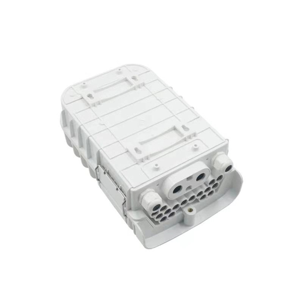
An optical line termination (OLT), also called an optical line terminal, is a device which serves as the service provider endpoint of a passive optical network. It provides two main functions: to perform conversion between the electrical signals used by the service provider's equipment and the fiber optic signals used by the passive optical network.to coordinate the multiplexing between the conversion. FeaturesOLTs include the following features: • A downstream frame processing means for receiving and churning an cell to generate a downstream frame, and converting a parallel dat. Most vendors integrate an entire fiber optic management system for ISPs to manage OLTs as well as client ONTs and as such are not interoperable. • • BT-PON.
[PDF]

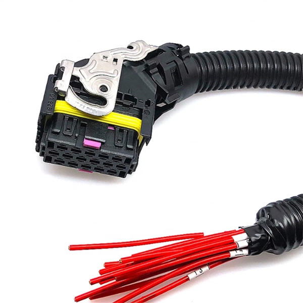
The optical module is usually composed of Transmitter Optical Subassembly (TOSA, containing a laser LD Chip), Receiver Optical Subassembly (ROSA, containing a photodetector PD Chip), a driving circuit, and an optical and electrical interface. Its schematic is shown in. This section explains the structure of a typical pigtail butterfly module, which gets its name from the two rows of seven leads at right angles on each side of the metal package plus an optical fiber pigtail at one end (Fig. Let's look at the internal structure (Fig. 2) of a common butterfly. Optical modules are devices used to connect network devices, transmit and receive data between network devices, and can be used to convert optical and electrical signals. The optical module is a very important component in an optical communication system. Optical devices are the core components of optical modules. TOSA and ROSA in Common Optical Transceiver Modules For ordinary optical transceiver modules, there are two optical devices, TOSA and ROSA, which have opposite effects.
[PDF]
The optical module serves as a crucial component in optical fiber communication systems, operating at the physical layer, which is the lowest layer in the OSI model. Its primary function is to achieve optoelectronic conversion by converting electrical signals into optical. ity and improved link performance. And now our EDGE8 solution delivers even more value – more applications, more options, more flexibility, more security, and more ways to seamlessly oducts without prior notification. Among various optical module form factors, SFP (Small Form-Factor Pluggable). Optical modules are electronic devices that convert electrical signals into optical signals for transmitting data over an optical fiber. These modules typically consist of a transmitter, which converts electrical signals into a light signal, and a receiver, which converts the received signal back. As an essential component of optical fiber communication, optical modules are optoelectronic devices that facilitate the conversion between optical and electrical signals during the transmission process. An. What is an Optical Module? The Ultimate Guide to Principles, Types, and Troubleshooting Optical Modules (also known as Optical Transceivers) are critical components in fiber optic communication systems.
[PDF]

Run the display transceiver [ interface interface-type interface-number | slot slot-id ] [ verbose ] command to view information about the optical module on a specified interface. In optical communication equipment, an optical module (Optical Module) contains several types of semiconductor chips that work together to complete the transmission and processing of optical signals. These chips typically include laser chips, photodetector chips, driver chips, transimpedance. When the optical module on an interface is faulty, you can run the display commands to view information about the optical module. Today, we will deeply analyze the four mainstream models of 100G QSFP28 dual-fiber optical modules: QSFP28-100G-SR4, QSFP28-100G-LR4, QSFP28-100G-ER4 and. The following uses the Moduletek SFP-10G-LR module connected to a Huawei S6700 switch as an example to introduce how to read information of the connected optical module on a Huawei switch. Figure 1 Schematic Diagram of Optical Module Connected to Switch 1. Optical Module Status Check Run the. Upgrade to 100G or 400G optics and save. Cisco Transceiver Modules - Learn product details such as features and benefits, as well as hardware and software specifications. Network administrators have a major challenge determining the right Cisco SFP modules, understanding complex model numbers that directly affect network performance and stability.
[PDF]

This quick-reference guide focuses on what to measure, how to interpret results, and what to do when findings indicate marginal performance. Whether you're a network engineer validating new inventory or an integrator preparing for deployment, knowing how to test optical transceiver modules can save time, reduce failures, and ensure SLA compliance. Unchecked optical modules can cause: Testing ensures compliance with IEEE 802. 3 and MSA. This article provides a comprehensive guide on measuring key performance indicators to evaluate the functionality of optical modules, with a specific focus on the sfp28 transceivers. A comprehensive understanding of the working principle of an optical module is essential for determining the. Evaluating the performance of optical modules is a practical discipline: you must verify optical power and signal quality, confirm electrical/optical compliance, validate link-level behavior under real traffic, and document results in a way that supports reliability engineering. This. The optical module serves as a crucial component in optical fiber communication systems, operating at the physical layer, which is the lowest layer in the OSI model. Its primary function is to achieve optoelectronic conversion by converting electrical signals into optical signals and vice versa.
[PDF]

As core components of optical communication systems, the proper installation and use of optical modules directly impacts network stability. The customer has 2 alarms on BTS3900 (GSM-R network). BBU Optical Module Transmit/Receive Fault 2. RF Unit Maintenance Link Failure The results of this alarms was restarting of the RF unit. After combining the RRU log analysis and the alarm of the optical module, the radio frequency maintenance. An alarm is generated when the transmit or receive power of an optical module is out of the allowed range. Indicates the MIB object ID of the alarm. Indicates the parent. After ruling out traditional problems like passive intermodulation (PIM), poorly aimed antennas and/or other coaxial problems, dirty fiber connectors account for 60 to 75% of the alarms, failures, and poor throughput problems found in modern cellular systems today. It has been several years since. All or part of the products, services and features described in this document may not be within the purchase scope or the usage scope. About This Document Introduction This document describes the routine hardware maintenance of the BBU3900. This article systematically identifies common anomalies during optical module installation. Combining hardware principles with practical experience, it.
[PDF]

BBU end can be connected to CWDM coarse wavelength division multiplexer through CWDM color optical module and OS2 single mode optical fiber patch cord, and then transmitted to CWDM coarse wavelength division multiplexer with one or two optical fibers. The operation of base stations requires a large number of optical modules for interconnection between devices, and we will talk about the application of optical modules in mobile communication base stations. Communication base station is composed of machine room, base station, antenna, feeder. The base station can be divided into two modules: the RRU for transmitting signals and the BBU for processing signals. The BBU is small and exquisite, with low power consumption, while the RRU is large and has high power consumption. In 4G networks, the optical modules used to connect BBU and RRU are mainly gigabit to 10Gbit optical modules. In modern server racks, the wrong optical choice can silently tax performance: queues grow, link training becomes flaky, and operators end up swapping modules mid-quarter. In 5G networks, CPRI is also upgraded to eCPRI. Currently, 5G of the bearer network mainly uses 25Gbps optical.
[PDF]

These installation instructions provide overview and specification information for small form-factor pluggable (SFP/ SFP+/SFP28) modules, as well as instructions for installing and removing the modules. Small form factor transceiver modules (including SFP, SFP+, and SFP28 modules) plug into the SFP. Some Extreme Networks switches support the use of 25 Gb SFP28 pluggable optical modules. Each module provides one 25-gigabit transmit and receive channel. Use of 25Gb SFP28 modules in QSFP28 ports requires the use of the QSFP28 to SFP28 adapter (part no. Use only Extreme Networks-certified. The ESR SFP28 module provides a 25 Gb optical connection using an LC duplex optical connector over one pair of OM3 or OM4 multimode fibers. One data lane operates in each direction, at 25 Gbps up to 200 meters using OM3 fiber or up to 300 meters using OM4 fiber. The fiber-optic SFP modules contain a laser that is classified as a “Class 1 Laser Product” in accordance. LINK-PP offers a full range of optical transceivers and SFP module for modern data centers, telecom networks, and enterprise infrastructures. Our portfolio spans data rates from 1G to 400G, including SFP, SFP+, SFP28, QSFP+, QSFP28, QSFP-DD, and OSFP modules, designed for both single-mode and.
[PDF]

Uses 12 wavelengths derived by shifting 6 traditional CWDM wavelengths left and right (±3. 5nm) using temperature tuning. Balances cost and channel density. Applications: Primarily 5G mobile fronthaul and midhaul networks requiring moderate capacity and cost efficiency. In fiber-optic communications, wavelength-division multiplexing (WDM) is a technology which multiplexes a number of optical carrier signals onto a single optical fiber by using different wavelengths (i., colors) of laser light. This technique enables bidirectional communications over a. This is the complete guide to Dense Wavelength-Division Multiplexing (DWDM) wavelengths and channels in 2024. Then, you will enjoy this new complete DWDM wavelength channels guide. What are the benefits of DWDM? #3. DWDM and CWDM enable carriers to deliver more services over their existing fiber infrastructure by combining multiple wavelengths on a single fiber. But navigating the alphabet soup of CWDM, DWDM, MWDM, LWDM, and SWDM can be daunting. 5 nm (800 GHz) in the O-band of 1270–1330 nm by using x-cut lithium-niobate-on-insulator (LNOI) photonic waveguides for the first time.
[PDF]