Source over 605 fiber-optic modules for sale from manufacturers with factory direct prices, high quality & fast shipping. FS provides 1/2/4G transceivers modules in SFP form factor, supporting transmission distances from 100m to 120km over SMF/MMF fiber and enabling low power and cost-effective connectivity solutions. Purchase from nearby warehouses. Trusted by 260K+ Enterprise Users. Fiber optic transceiver modules are fiber cable adaptive housings that contain a light source for transmitting data via fiber optic cable as well as a photodiode for receiving fiber optic data. Mounting options include pluggable CXP, QSFP, SFF, SFP, and XFP, surface or through-hole, CFP, 1x9 SC. This article covers both custom optical elements and custom optical assemblies or systems — beginning with the former. Many optical elements such as lenses, laser mirrors, prisms and diffraction gratings are fabricated as standard parts, i., they are made with the same specifications for many. $ 3,869. 00 Original price was: $3,869. Sale! Sale! Sale! Sale! $ 369. 00 Original price was:. Edmund Optics ® manufactures and supplies customers around the globe with millions of precision optical components and optical assemblies. Our manufacturing capabilities comprise of expertise and resources necessary to manufacture optical products based on your project's specific requirements. Our. TAKFLY COMMUNICATIONS CO. Fiber optical modules Humpal SFP module.
[PDF]
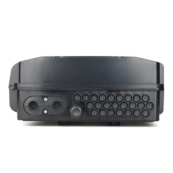
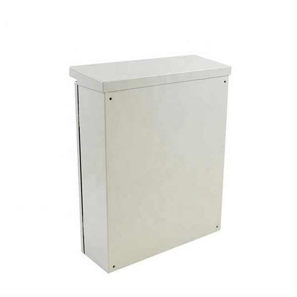
While Polycarbonate often carries a higher upfront cost than a standard PVC electrical enclosure or ABS electrical enclosure, its structural durability, capacity to meet IP66 enclosure ratings, and resistance to UV degradation result in fewer field failures and lower replacement costs. A comprehensive range of products and solutions designed specifically for extreme temperature applications, ensuring the utmost in safety and reliability. Explore our selection of junction/terminal boxes, luminaires, receptacles and other tools for extreme temperatures. For. The junction box XAWG range Ex e in glass-fiber reinforced polyester enclosures are designed for use in any environment where an explosive atmosphere may be present and are suitable for chemical agent environments, seawater. Prolonged exposure to harsh chemicals, for example, can weaken the metal and lead to potential deformation or cracking. However, with proper maintenance and by choosing enclosures with the. The right choice of junction box ensures safety, extends equipment life, and helps meet compliance standards. Because not all environments are the same, junction boxes come in various materials, ratings, and designs.
[PDF]
The system in this example contains the following elements: 1. 2 Pseudo-random Bit Stream (PRBS) block 2. 2 NRZ Pulse Generator (NRZ) 3. 1 CW Laser (CWL) 4. 3 1x2 Fork (FORK) 5. 2 Electrical Not Gate (N.
[PDF]

A neat, well-organized subpanel bundles wires to conserve space and improve access. Ideally, wire groups are installed in layers and wires are bent at right angles to buses or breakers. Label short sheathing sections (slugs) to indicate which circuits wires serve. A cluttered or messy junction box can lead to electrical hazards, such as short circuits or difficulty diagnosing issues later on. Whether you're a professional electrician or a DIY. Welcome to this live training session! ⚡ In today's tutorial, I'll be demonstrating how to arrange cables neatly inside a distribution bo. more See what others said about this video while it was live. After all, a well-organized junction box is like a well-organized sock drawer: you might not notice it, but when it's a mess, everyone knows. And let's be honest—nobody wants to dive into a rat's. Whether you're a homeowner or working with a residential electrician in Richmond VA, managing your cables properly makes your space look better, increases safety, and improves functionality. Learning how to keep wires organized not only improves the appearance of your space but also makes your. To ensure the aesthetic appearance of the wiring installation inside the electrical ready board box, the following points can be followed: Grouping and layering: Grouping and layering neutral, live, and ground wires to ensure clear and orderly routing of the lines. Horizontal and vertical: When.
[PDF]

Communication networks are an integral part of interconnected transmission lines in a power grid, analogous to the spinal cord for control signal and information exchange among substations, data hubs, and load dispatch centers. This article cov. Communication networks are an integral part of interconnected transmission lines in a power grid, analogous to the spinal cord for control signal and information exchange among substations, data hubs, and load dispatch centers. This article covers the major trend and design aspects of fiber optics communication link in power transmission line netwo. The communication network in the power grid is one of the most interrelated systems that require perfect compliance in equipment and protocol selection. While the high voltage components are relatively unchanged over decades in terms of operating principles, the communication protocols and equipment are seeing astonishing advancements every year. S. 2.1 Knowhow of prevailing setupWhile the primary objective is always to get the best solution for the lowest price, in the case of extension projects, the design engineers must also keep an eye on the existing setup. The issue of back-compatibility and upgradationsshould be properly accessed in existing equipment, even more so in the case of proprietary legacy setups. Figure below illustrates one such group of communication equipment in existing substations that might need proper interfacing and compatibility adapters befo.
[PDF]
The PL-1000D simultaneously monitors up to 16 fiber strands, eight on the OTDR and eight on the OSA, and operates standalone over dark fiber, lighted fiber, or a third party network without impacting network traffic. The device monitors the entire D. The PL-1000D simultaneously monitors up to 16 fiber strands, eight on the OTDR and eight on the OSA, and operates standalone over dark fiber, lighted fiber, or a third party network without impacting network traffic. The device monitors the entire DWDM C-band spectrum and provides the optical spectrum, OSNR, and OTDR measurements of the fiber. The OTDR locates fiber cut by sending high powered optical pulses into the fiber and creating Rayleigh back-reflections. The returning signals are measured and calculated, indicating the accurate location and intensity of the fault. The OTDR supports GIS (Geographic Information System) using Rest API, enabling precise geographic location of disrupt. The OSA enables the user to monitor the OSNR and optical spectrum of each fiber and shows a full, accurate and detailed picture of the wavelengths used in the fiber. OSADiagram Graphical Display of the OSA, from PacketLight's LightWatch NMS Please contact usfor a quote or further assistance.
[PDF]

Run the following command to view detailed optical module information on the device interface: display transceiver interface <interface-type> <interface-number> verbose The command output is divided into two parts:. Run the following command to view detailed optical module information on the device interface: display transceiver interface <interface-type> <interface-number> verbose The command output is divided into two parts:. When the optical module on an interface is faulty, you can run the display commands to view information about the optical module. Related Information Video Identify a Huawei-Certified Optical Module Run the display transceiver [ interface interface-type interface-number | slot slot-id ] [ verbose ]. During use, reading optical module information helps understand its real-time operating status, enabling faster troubleshooting of link abnormalities. The following uses the Moduletek SFP-10G-LR module connected to a Huawei S6700 switch as an example to introduce how to read information of the. See the interface module via the optical display command information, including general information of the optical module, manufacturing information, and alarm information. If it is not a Huawei-certified optical module, replace it with a Huawei-certified optical module. If the optical module is installed on a GE port, run the display interfaceGigabitEthernet x/x/x command to view port information when the optical module.
[PDF]

Professional Cable Tray Elbow Making | Metal Fabrication Tutorial Learn how to make cable tray elbows professionally with step-by-step guidance. This video shows metal fabrication techniques, DIY cable tray projects, and tips for perfect bends and joints. Whether you are a DIY enthusiast. The method for producing bridge bend elbows is as follows: Take a 90-degree cable tray bend elbow as an example, and apply the same principles for 45-degree bends accordingly. The length of the bottom side (bottom diagonal) after bending the cable tray should be equal to the width of the cable. This manual is designed to guide workers through the detailed production process of ladder cable trays, including the manufacture of horizontal elbows, tees, crosses, reducing bends, and vertical bends, with emphasis on precision, safety, and quality control. What's Involved in Producing Ladder. The bends, tees, crosses, risers and reducers of wire mesh cable tray can be easily and quickly made live at the project by using a bolt cutter. Since the jaws of the bolt cutter drags a layer of zinc across the cut end and forms a protective layer. When a wire cable tray is cut, the fact that a. How to bend 22. 5 DEGREE OF CABLE TRAY 3 LA. How to bend 90 degree of cable tray 3 line with the same distance :// • HOW TO BEND 90 DEGREE OF CABLE TRAY 3 LINE. Enjoy the videos and music you love, upload original content, and share it all with friends, family, and the world on YouTube.
[PDF]

Whether you're an electrician or a DIY enthusiast, this tutorial will help you understand the fundamentals of wiring a distribution box for a residential setup. Hey, in this article we are going to see the Single Phase Distribution Box Wiring Diagram and Connection Procedure. A distribution board or distribution box is where the main power supply is distributed to multiple loads. And all the switching and protective devices are installed in the. The DB panel board controls the flow of electricity. It protects homes and industries from electrical hazards. It ensures that circuits are safe, organized, and easy to manage. A properly installed electrical distribution box is important for. Electrical systems power our homes, offices, and industrial facilities, but behind every reliable electrical setup lies a crucial component that often goes unnoticed: the distribution box. This essential piece of equipment serves as the nerve center of your electrical system, managing power flow. Welcome to our channel @Electricalgenius In this video, we'll take you through a detailed step-by-step guide on wiring a home distribution DB (Distribution Board) box. Distribution. Distribution box The system diagram usually shows the electrical connection and configuration inside the distribution box in a graphical way, including busbars, circuit breakers, fuses, load devices and other elements. In practical applications, the corresponding system diagram can be drawn.
[PDF]

This guide shows you how to organize circuit breaker wiring properly. You will learn to build a safe, efficient, and professional electrical system today. Circuit breaker wiring configurations involve organizing main switches, busbars, and branch breakers within a distribution box. Messy distribution boxes are dangerous and very hard to fix. You lower the chance of circuits getting too hot or overloaded when you pick the right box for your needs. When installing or troubleshooting a power distribution system, understanding how to correctly connect the main electrical supply to the control panel is crucial. Professional electrical panel schedule tool for creating detailed load distributions, calculating circuit loads, balancing phases, and ensuring NEC compliance for electrical distribution panels. Panel schedules are essential for electrical system documentation, load analysis, and NEC compliance. Material preparation: Prepare the required circuit breakers, wires, wiring ties and other materials, and ensure that they meet the design drawings and installation requirements. Location determination: Determine the installation position of the circuit breaker according to the position of the. Hey, in this article we are going to see the Single Phase Distribution Box Wiring Diagram and Connection Procedure. And all the switching and protective devices are installed in the.
[PDF]
For TDM-PON, a passive optical splitter is used in the optical distribution network. In the upstream direction, each ONU (optical network units) or ONT (optical network terminal) burst transmits for an assigned time-slot (multiplexed in the time domain). In this way, the OLT is receiving signals from only one ONU or ONT at any point in time. In the downstream direction, the OLT (usually) continuously transmits (or may burst transmit). ONUs or ONTs see their own data through the address labels embe.
[PDF]

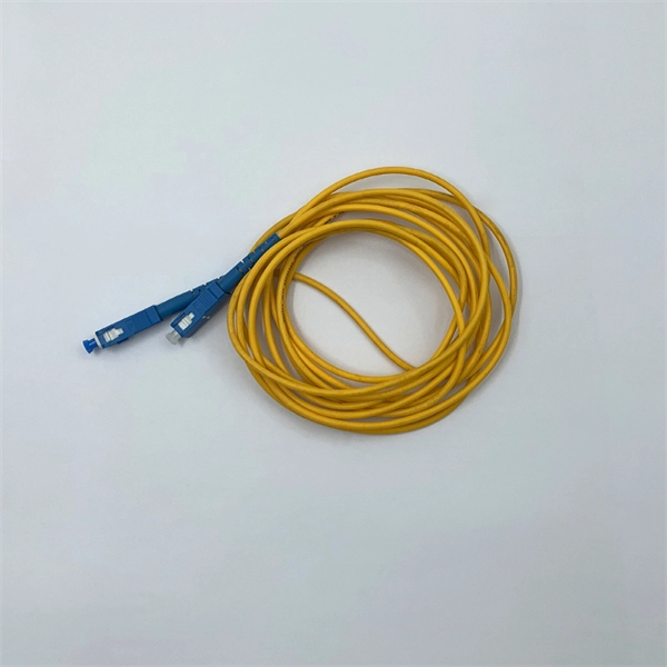
The LC optical fiber pigtail is designed with a push-pull mechanism, enabling easy installation and removal without compromising on performance. Executive Summary: A fiber optic pigtail is one of the most commonly specified yet least understood components in structured cabling. Get the wrong connector type, the wrong polish, or skip proper fusion splicing technique—and you're looking at elevated signal loss, increased back reflection, and a. Fiber pigtails are simple in appearance, yet essential in function. They are the bridge between fiber optic cables in the field and the equipment or patch panels that manage them. By combining factory-installed connectors with spliced bare fiber, pigtails ensure that network installers can create. Fiber optic network design refers to the specialized processes leading to a successful installation and operation of a fiber optic network. It includes first determining the type of communication system (s) which will be carried over the network, the geographic layout (premises, campus, outside. All Rights Reserved. fCONSTRUCTION QUALITY REQUIREMENTS FOR FTTP & SSP Work Orders This document provides Construction Technicians, Construction Managers, FTTP/SSP Vendors, and Inspectors with the essential information to ensure a quality build and to successfully pass an Outside Plant Inspection. These terminations must be of the right style, installed in a.
[PDF]
The 2025 Fiber Deployment Cost Annual Report, produced by the Fiber Broadband Association and Cartesian, provides the industry's most comprehensive benchmark of fiber build costs across the U. Drawing on data from operators and contractors in 38 states, the report shows that. Fiber optic network projects for industrial and oil and gas applications typically cost $15,000-50,000 per mile for aerial installation and $30,000-80,000 per mile for direct burial. Budgeting requires accounting for design, permitting, materials, labor, splicing, testing, and a 15-20% contingency. Buyers typically pay for fiber laying by combining material costs, labor time, and permitting plus trenching or aerial support fees. The main cost drivers are trench depth, fiber count and type (single-mode vs multi-mode), conduit requirements, and local permitting rules. This guide provides clear cost estimates, price ranges. Site Survey and Planning The first and most critical step in fiber optic network construction is the site survey—also known as a field survey. Engineers and planners assess the project area to determine the most efficient routes for the fiber optic installation. This information can help project leaders engage with providers and network operators in their area. This data is based on cost information.
[PDF]