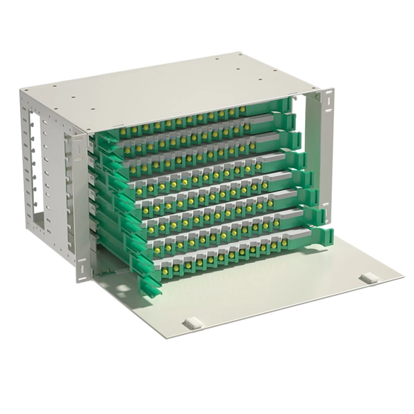
Given the access to a fusion splicer, you can splice the pigtail right onto the cable in a minute or less, which greatly speeds the splicing and saves significant time and cost spent on field termination. A fiber optic pigtail is a short length of optical fiber cable with a factory-terminated connector on one end and a bare, exposed fiber on the other. Unlike a patch cord—which has connectors on both ends—the bare fiber end of a pigtail is designed to be permanently spliced (either by fusion or. The Contractor tasked to perform testing or splicing on any fiber optic cable will follow these testing standards to fulfill their contractual obligations. The Contractor must utilize the correct equipment and testing techniques to gain acceptance, or the work cannot be approved. While for mechanical fiber optic pigtail splicing, it precisely holds a fiber optic pigtail. Fiber optic fusion splicing is on the rise and Corning's Pigtailed Splice Cassettes enable faster field splicing and easy modular management of connectorization within the housing. Pre-routed and preloaded, pigtailed splice cassettes reduce installation time by up to 40%. Today, fusion splicing. Next, we will introduce three common types: SC, FC, ST fiber optic pigtails. 5mm pre-radiused ferrule which is made of zirconia or stainless alloy.
[PDF]

A wiring diagram for a photocell and timeclock controller provides a step-by-step guide for installing and connecting all the components in a light system. It shows exactly how each component fits into the overall scheme of things, as well as what wires to use and which connections to. Intelligent Lighting Controls' wiring diagrams show detailed schematics of our solutions. A lighting control module is the “control center” for your lighting system. It acts as a bridge between your physical lighting fixtures and the smart systems that manage them. Instead of relying solely on traditional wall switches, you can control your lights via remotes, mobile or web apps. This guide will discuss the steps needed to integrate with URC Total Control. Commission CSI Controllers Step 2. Locate/Download latest TCM files/Module Step 3. Network Setup Step 6. Supports DALI V2 compatible switches and sensors, works out of the box. Simple and easy setup. ControlByWeb® IoT controllers are a great fit for lighting control in edge applications. Understanding the components that make up a modern lighting system, and how they relate to one another is key to ensuring the best performance and.
[PDF]
An optical time-domain reflectometer (OTDR) is an optoelectronic instrument used to characterize an optical fiber. It is the optical equivalent of an electronic time domain reflectometer which measures the impedance of the cable or transmission line under test. An OTDR injects a series of optical pulses into the fiber under test and extracts, from the same end of the fiber, light that is scatter. Reliability and quality of OTDR equipmentThe reliability and quality of an OTDR is based on its accuracy, measurement range, ability to resolve and. The common types of OTDR-like test equipment are: 1. Full-feature OTDR: 2. Hand-held OTDR and Fiber break locator: 3. RTU in RFTSs:. In the late 1990s, OTDR industry representatives and the OTDR user community developed a unique data format to store and analyze OTDR fiber data. This data was based on the specifications in GR-196, G.
[PDF]

We will look at how to interpret PLC LED status indicators for digital inputs and outputs and how to perform troubleshooting tests using a Digital Multimeter. This section includes the block diagram of the DI 16x24VDC ST module with the terminal assignments for a 1-wire connection. Information on wiring the BaseUnit can be found in the system manual ET 200SP distributed I/O system. The load group of the module must begin with a light-colored BaseUnit. How to wire real-world signals into the Logo's digital inputs to detect whether a machine is running. Covers stack lights, door sensors, relay contacts, and proximity switches — with a complete wire diagram and step-by-step instructions for both electrical engineers and IT teams. You have a Siemens. PLC and DCS control systems Wiring Diagrams for Digital Input (DI), Digital Output (DO), Analog Input (AI), and Analog Output (AO) signals. be responsible or liable for indirect or consequential damages resulting from the use or application of this equipment. The examples and diagrams in this manual are included solely for illustrative purposes. Because of the many variables and requirements. This manual contains information that is necessary to use the NX-series Digital I/O Unit. PLC programs rarely cause failures, so in this article, we'll assume that there are no program errors and that the fault originates in the.
[PDF]
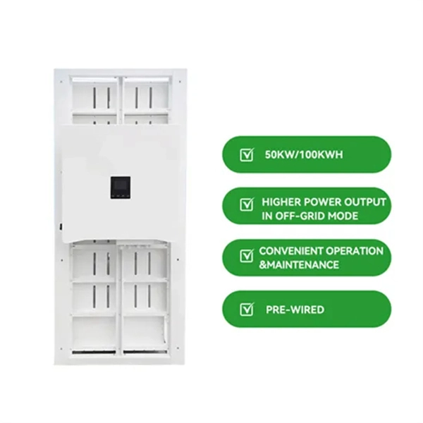
Leaders will gather at the World Economic Forum Annual Meeting 2026 to discuss how to protect the environment while also driving economic growth. The next phase of global growth will be shaped by digital intelligence and the energy infrastructure that supports it. The Global Energy Interconnection (GEI) Journal publishes original research on theories and developments as well practical applications on principles of large scale low carbon energy generation, transmission, distribution & storage technologies, global energy interconnection & system developments. The provision of low carbon energy to our society is a key issue at the heart of sustainable development of global energy supply. China's concept of Global Energy Interconnection recognizes the importance of energy inter-connectivity for clean energy transition and repre-sents one of the boldest visions for low-carbon development at the national, regional strial Revolution in the 1870s.
[PDF]
For TDM-PON, a passive optical splitter is used in the optical distribution network. In the upstream direction, each ONU (optical network units) or ONT (optical network terminal) burst transmits for an assigned time-slot (multiplexed in the time domain). In this way, the OLT is receiving signals from only one ONU or ONT at any point in time. In the downstream direction, the OLT (usually) continuously transmits (or may burst transmit). ONUs or ONTs see their own data through the address labels embe.
[PDF]

The OPM 510 and 520 are available in standard and high-power versions for the Telco and MSO markets. The OPM510 and OPM520 supports wavelengths of 850, 980, 1270 1300, 1310, 1490, 1550, 1577, 1623 and 1650nm. The rugged enclosure provides confidence when testing singlemode and. Count on Tempo Communications Optical Power Meters (OPM510/520) to test and maintain your fiber optic networks. Our optical power meters feature built-in calibration factors. Optical power meters and detectors have been served by Newport for over 30 years. The offering ranges from a low cost, hand-held meter to the most advanced dual channel benchtop power meter available in the market. Our 1936-R/2936-R series boasts state-of-the-art analog boards with a whopping 250. © Copyright© Santec Holdings Corporation. Demo the full range, from multi-use to dedicated PON and FTTH. VIAVI offers fast, cost-effective, and easy-to-use power meters for installation and maintenance of single mode and multimode fiber optic networks and. AFL is a trusted supplier of optical testing equipment with more than 30 years of experience and tens of thousands of units in use in the field. AFL's full range of power meters are used for testing single-mode and/or multimode fiber networks. Power meters with wave ID can detect two or more.
[PDF]

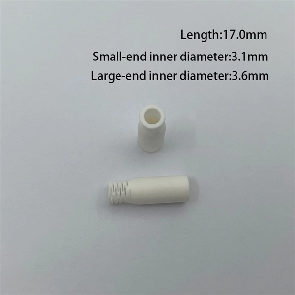
A ceramic sleeve is a small, cylindrical element employing zirconia, which is a strong, low thermal expanding ceramic used in a fiber optic system to locally align and hold the interface between the fibers or connectors. It ensures precise alignment. Known for their high-temperature resistance, wear resistance, and chemical stability, ceramic sleeves have become a key element in applications spanning communications, electronics, automotive, aerospace, and industrial systems. The industry is developing in a diversified manner, connecting raw. Most of the ferrules used in optical connectors are made of ceramic (Zirconia) material due to some of the desirable properties they possess. Kyocera's extrusion molding process creates ferrules with excellent coaxiality, and our precision machining ensures excellent concentricity with precise. Alignment sleeves are the primary mechanical reference inside a fiber optic adapter. Their role is to constrain lateral offset, angular deviation, and axial separation between mating ferrules, directly determining insertion loss and return loss stability. Historically, both ceramic and phosphor. The global market for ceramic sleeves is experiencing robust growth, projected to reach an estimated $287 million by 2025. This expansion is fueled by an impressive CAGR of 20. 5% during the study period. The primary drivers for this surge are the increasing demand for high-performance optical.
[PDF]
Atomic spectroscopy uses the electromagnetic radiation or mass spectrum of a sample to determine elemental composition. The wavelength of energy absorbed or emitted by atoms is characteristic to each element and can be used for element identification and quantification. Atomic spectroscopy is a technique that studies the interaction of light with atoms to reveal information about their electronic structure. It relies on the principle that when electrons in an atom change energy levels, they emit or absorb light at specific wavelengths unique to that element. Samples must be in liquid form before being placed in the analyzer. To do this, a chemist will use certain acids (nitric or hydrochloric) to extract the metallic component of a sample. It can be divided by atomization source or by the type of. Analytical atomic spectrometry comprises a considerable number of techniques based on distinct principles, with different performance characteristics and hence with varied application scopes, but in all cases providing elemental chemical information about the composition of samples. This abstract provides an overview of the key principles, techniques, applications, and recent advancements in the field of atomic spectroscopy. Atomic. Atoms consist of a nucleus surrounded by electrons, which occupy specific energy levels or orbitals. The energy levels of an atom can be described using the following equation: E_n = -frac.
[PDF]
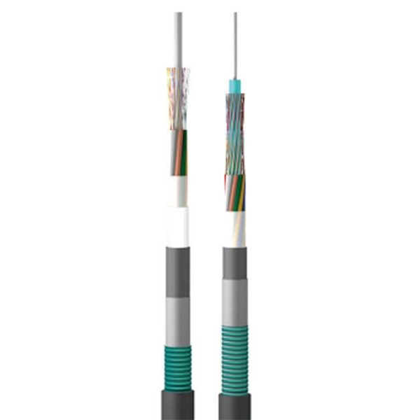
Hot-dip galvanizing offers an exceptional solution for protecting cable trays from rust and corrosion. This process forms a robust, long-lasting zinc coating that not only extends the lifespan of the trays but also reduces maintenance costs. Whether installed outdoors or in environments prone to. The cable tray finishes are particularly important for ensuring the system's durability and performance, as the finish helps protect the trays from environmental factors such as moisture, chemicals, and corrosion. Additionally, proper cable tray support span calculation, adherence to installation. Electro-galvanized cable trays are coated with a layer of zinc through an electroplating process. This thin zinc coating provides protection against corrosion, particularly in indoor environments where the trays are not exposed to extreme weather conditions. Cost-effective: One of the more. Hot-dip galvanized cable trays, like those manufactured by Tech&Tray (techtray. org), undergo a process where they're dipped in molten zinc at high temperatures (approximately 450°C). The zinc chemically bonds with the steel, creating long-lasting corrosion protection that works even if the surface. The galvanization process means an additional coating of hot zinc material, which helps offer healthier usage durability. Steel is coated with zinc through electrolysis by dipping steel into a bath of.
[PDF]
Fluorescent fiber sensors that fluoresce along the length of the fiber offer an advantage for detecting partial discharge (which generates UV and visible light), since light absorbed from any angle, along the entire length of the fiber, may be detected. Fluorescent materials integrated on the tips of optical fibers, for example, provide a means to perform fluorescence thermometry while monitoring the intensity or the spectral variations of the fluorescence signal. Similarly, certain molecules can be tracked by monitoring their characteristic. Fluorescence can be very simply defined as the emission of light when a material is exposed to electromagnetic radiation. This emission may continue for a period of time after the initial excitation. The length of time that a material will emit is a product of a number of interactions that occur at. Optical fiber sensors (OFSs) have emerged as essential tools in the monitoring of physical, chemical, and bio-medical parameters in harsh situations due to their high sensitivity, electromagnetic interference (EMI) immunity, and long-term stability. However, the current literature contains. Fluorescent fiber sensors fluoresce when light of various wavelengths is absorbed by the fiber.
[PDF]