Identify the Pins: Ensure you correctly identify the live (L) and neutral (N) pins. Connect to Power Source: Insert the 2 pin plug into a compatible power outlet. The 2 pin connector is one of the most versatile and simple connectors. It can be used for a variety of different applications. These small, yet powerful components are found in nearly every device--from smartphones to industrial machinery--connecting electrical circuits and ensuring the smooth. A 2-pin DC power connector offers a compact and efficient solution. In this guide, you'll learn exactly what these connectors are, where they're used, and how to choose the best one for your application. It is commonly found in household appliances and electronics. Neutral Pin – Completes the circuit by returning the current. Since there is no earth pin, these plugs are suitable only for devices with double. The cold-pressed wiring of electrical heavy-duty connectors mainly includes the following steps: 1. Prepare tools and materials: You need to prepare cold-pressed terminals, wire strippers, wire crimping pliers, screwdrivers and other tools and materials. I go over all the components and steps to put together a 2 pin Deutsch connection.
[PDF]

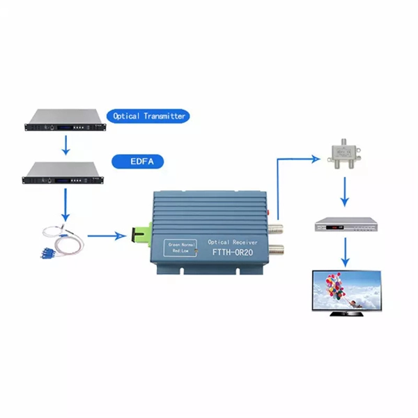
In this step-by-step guide, we will walk you through the process, ensuring that you can seamlessly connect your optical cable and enjoy a clear and uninterrupted audiovisual experience. Optical cables are becoming increasingly popular for transmitting high-quality. Optical audio cables can easily improve your TV's sound by connecting to external speakers. Learning how to connect an optical cable is easy, but there are a couple of gotchas that you should know. Here are the basics: Identify the optical output; if there's a protective plastic cap, remove it. The most common types are: The Toslink optical cable is a standard for transmitting digital audio signals. It uses a plastic or glass fiber to carry light signals from one. You can connect an older flat screen TV to ANY Stereo system, Surround Sound system, or Soundbar. This video shows you step by step how to make audio connections using an digital optical cable. You can use an optical connection even if your audio system does not have an optical socket, and by using. One of the easiest ways to achieve high-quality sound is to connect your TV to a home theater system or soundbar. Easily connect your optical audio cable to your TV! Follow our step-by-step guide for a hassle-free setup and enjoy crystal-clear sound. No wonder how to improve TV sound, right? When the sound is weak, for example, when using an analog sound source, then an optical audio cable possibly will be the.
[PDF]

Download the list of Fiber Optic Products Suppliers in Western Asia as of May 05, 2025 with and without website information. 25% increase from 2023. 10% of all Fiber Optic Products Suppliers in Western Asia are single-owner operations, while the remaining 7 which. Here are the top-ranked fiber optic connector companies as of May, 2026: 1. Thermalogic Corporation, 2. These. Fiber Optic Connectors are an essential component of any fiber optic network that provides a secure and reliable connection between two fiber optic cables. The leading manufacturers of Fiber optic connectors are listed below. Narrow down on the list of companies based on their location and. AFL, based in Duncan, South Carolina, is a prominent manufacturer of fiber optic products and solutions. Established in 1984, the company has built a reputation for delivering high-quality products that cater to the telecommunications and industrial sectors. AFL's extensive product line includes. UnitekFiber produces high quality of MPO|MTP Cables, Fiber Optic Patchcords, SFP Optical Transceivers, MPO|MTP Patch Panels and Outdoor Fiber Cables. We design, create and deliver reliable and cost effective fiber optic products to meet customers' business goals. Our international database.
[PDF]

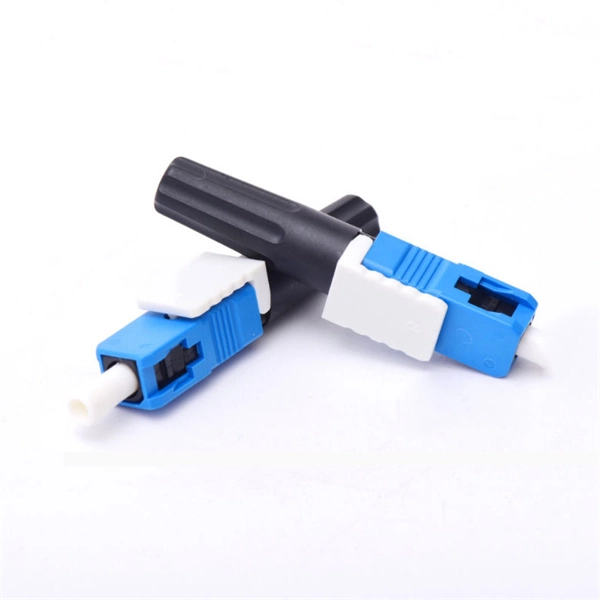
This guide delves into the structure and working principle of fiber optic connectors and outlines the critical steps for creating a successful connection. There are many types of fiber optic connectors, including SC, LC, FC, ST, D4, MU, MT/MPO, etc. These connectors can be divided into single-mode and multi-mode fiber optic connectors according to their structure and purpose. To learn more about the types of fiber optic connectors, click here: Types. Proper connection of fiber optic cables is essential to harness these benefits fully, as even minor errors can lead to significant performance issues like signal loss. This article will guide you through the necessary tools, materials, and methods on how to connect fiber optic cables effectively. At the heart of any robust fiber optic network lies a crucial process: Preparing a fiber cable for termination of a connector or splice. Fiber optic connectors play an essential role in the realm of optical communication, enabling seamless connections between fiber optic cables. We terminate fiber optic cable two ways - with connectors that can mate two fibers to create a temporary joint and/or connect the fiber to a piece of network gear or with splices which create a permanent joint between the two fibers. Whether you are installing a new network or repairing an existing one, ensuring a proper connection is crucial for maintaining optimal signal.
[PDF]

Fiber optic connectors can be categorized according to different standards such as utilization, fiber count, fiber mode, and transmission method. They are also divided into single-mode and multimode types based on their distinct characteristics. This guide will walk you through the most common fiber connector types, explaining their characteristics, advantages, and typical use cases. Whether you're planning an FTTH deployment, upgrading a data center, or working in telecom infrastructure, this guide will help you make informed decisions. Compared to Copper cables, Fiber connector types are incredibly varied. Where copper twisted pairs tend to terminate with an RJ45 plug, fiber optic connectors come in all sorts of shapes and sizes, with all manner of different use cases in mind. An optical fiber connector is used to join optical. With a wide variety of connector types available, choosing the right connector for your network can be challenging. Learn how each connector works, where it's used, and how to choose the right option for today's high-density, high-speed networks. It is a precise coupling device that joins fiber optic cables quickly, enabling faster connection and disconnection than splicing. The connector mechanically orients the fiber cores, allowing light to pass and travel through. In this guide, you'll explore various types of fiber optic cable connectors, each with unique features and best uses. We'll also provide practical advice.
[PDF]
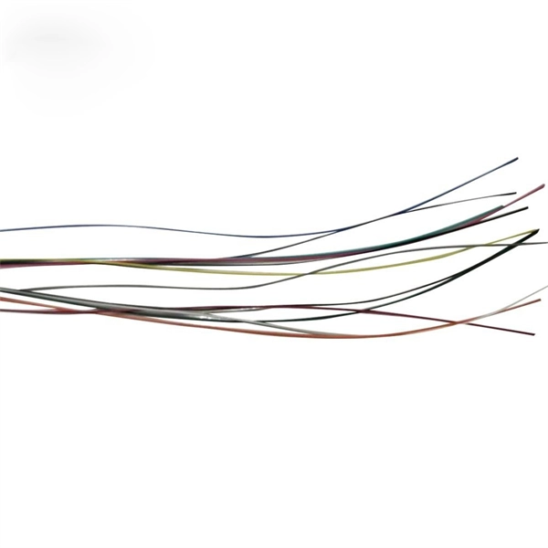
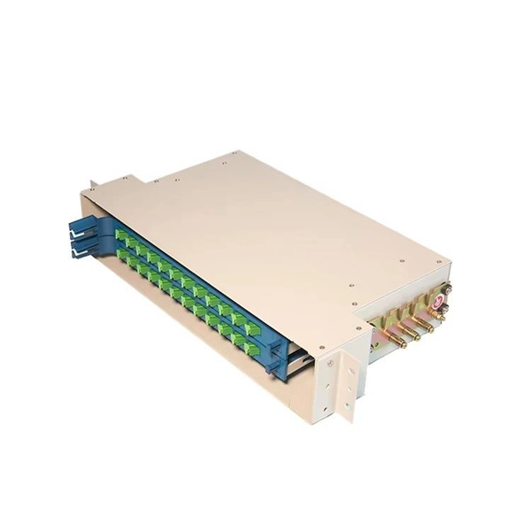
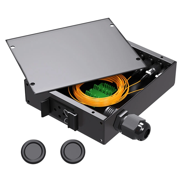
The bare fiber end is designed to be fusion spliced or mechanically spliced to the fiber optic cable in the field. This design makes pigtails the ideal choice for applications where fibers from a large cable must be terminated at an ODF (Optical Distribution Frame), terminal box, or. By combining factory-installed connectors with spliced bare fiber, pigtails ensure that network installers can create fast, reliable, and cost-effective terminations. Without pigtails, every termination in an ODF, terminal box, or splice closure would require field-installed connectors—an approach. ■ What is a fiber optic pigtail cable? A pigtail fiber indicates a short length of optical fiber cable that has a pigtail connector (for example, SC, FC, ST, LC, etc. This. A fiber pigtail is typically a fiber optic cable with one end factory pre-terminated fiber connector and the other exposed fiber. It is usually suitable for field termination using a mechanical or fusion splicer. Its primary function is to connect active network devices (e., switches, routers, transceivers) to passive components (e., patch panels, ODFs) or other devices. Think of it as a.
[PDF]
Thank you very much for purchasing Panasonic products. Read this Instruction Manual carefully and thoroughly for the correct and optimum use of this product. Kindly keep this manual in a convenient place fo.
[PDF]

GOOD WILL INSTRUMENT (SUZHOU) CO. Browse online or download User Manual for Equipment Gw-instek GOS-652G. GW Instek GOS-652G User Manual 50MHz Cursor Readout With Delayed Sweep.. GOS-658G 20MHz Cursor Readout... GOS-652G 35MHz. Caution statements identify conditions or practices that could result in damage to this product or other property. THIS APPLIANCE MUST BE the letter E or by the earth symbol or coloured Green or Green & Yellow. EARTHED The wire which is coloured Blue must be connected to the terminal which is. y have a fraction of the total loss compared to fiber-based equivalents. FBG also provides a latency in the o der of nanoseconds as compared to microseconds in fiber-based solutions. The FBG based DCMs are designed to perfectly mimi the dispersion and dispersion slope characteristic of G. 652 fiber. g sensitivity and low water-peak level. Together they allow unlimited use of the whole telecom wavelength win ow for a great variety of applications.. GOS-653G Basic... GOS-622G. The GOS-653G/652G Series is an example of classic analog oscilloscope design. The GOS-653G /652G cover a broad range of industry applications, such as product design, assembly lines, repair & servicing, and educational purposes for EE laboratories and class experiments. Coupled with various trigger.
[PDF]
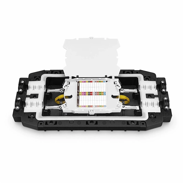
Calculate split loss, excess loss, and terminations for any ratio quickly today. See power budget impact instantly, then download a CSV or PDF summary. Use 2×N when two inputs feed the same distribution stage. Common values: 2, 4, 8, 16, 32, 64. Wavelength is recorded in. Fiber optic joints or terminations are made two ways: 1) splices which create a permanent joint between the two fibers or 2) connectors that mate two fibers to create a temporary joint and/or connect the fiber to a piece of network gear. Either joining method must have three primary characteristics. Optical fiber channel insertion loss is the decrease in optical power that occurs when an active transmitter is linked to an active receiver via terminated, optical fiber cables and patch cords and may include splice points and optical couplers. In general, loss is the natural decay of a signal. Telcordia and TIA allow a 0. 3 dB maximum splice loss. Connector loss is always measured as a mated pair. ITU & IEC allow 0. Splitter loss values are "Typical" and include a connector in and out. These terminations must be of the right style, installed in a. In this lesson, a long and very important one, you will learn about fiber splicing and termination. Wavelength is recorded in outputs for documentation.
[PDF]
There are several diagnostic methods to help troubleshoot fiber optic connectors, and the diagnostic method is to cross-section the fiber optic connector. This technology allows us to actually look inside the fiber optic connector to see defects and pinpoint the cause of. Fiber design and transmission technology have collaboratively evolved to increase bandwidth. Dig-ups dominate! Cablers have very little influence on the majority of causes of cable field failures. While a small percentage, we can examine the “intrinsic” cable failures and what is done to prevent. Connector failure is most frequently the result of a dirty or damaged end-face. Fiber-optic connector: SC type In the connector, the element that holds the fiber and provides the alignment positioning is the ferrule. The. In August of 1999, Boeing Corporation (Boeing) engineers being used on International Space Station flight a defect in the glass fiber (see Figure 1, “Rocket and NASA engineers and managers, Boeing created and reliability of the cable installed in the U. Fiber coupling can be accomplished by fusion splicing.
[PDF]
The Asia-Pacific fiber optic connector in telecom market is analyzed and market size insights and trends are provided by country, product type and cable type as referenced above. The countries covered in the.
[PDF]
Here's a quick guide to make sure your fiber optics sail through the cold season: While fiber optics are tough, cold temps can cause trouble. Water in cables can freeze, potentially harming connections. Ensure tight seals on cable joints and connectors to. The fiber carries data as pulses of light, and has nowadays overtaken copper wire as the medium of choice – primarily because it is lower cost, faster and less bulky. Optical fiber is also harder to hack than copper, making it more secure and safer because it doesn't generate heat. There is. Fiber optic cables are the backbone of modern high-speed data transmission, offering unparalleled speed and reliability compared to traditional copper wires. Summary : Winter weather generally has minimal impact on fiber optic cables since they transmit data through light rather than electricity, making them resistant to temperature-related signal loss. Waterproofing prevents icy.
[PDF]
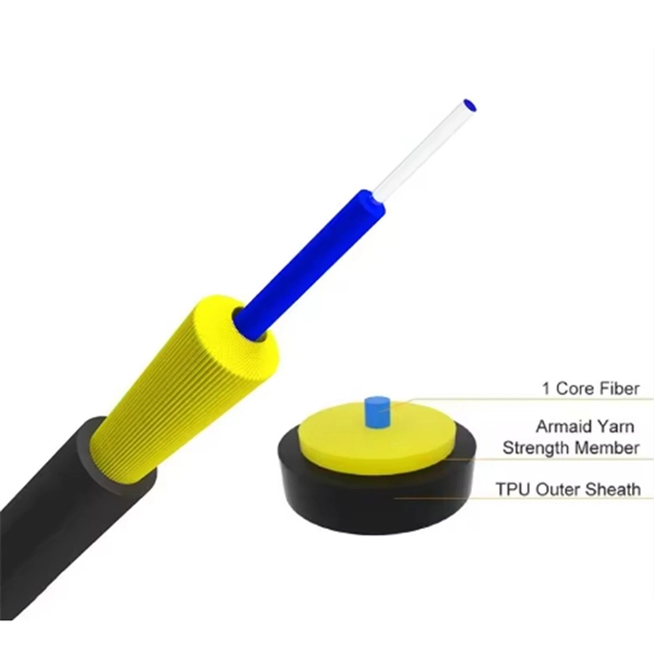
GYTS is a model designator for outdoor fiber optic cable. 'G' indicates it's for outdoor use, 'Y' for its Polyethylene (PE) sheath, 'T' for the gel-filled loose Tube structure, and 'S' for the corrugated Steel tape ar.
[PDF]
To properly remove the optical cable: Locate the port > Stabilize the device > Gently grasp & pull the plug (not the cable) straight out > Do the same with the other end > Cover both connectors with plastic tips. To remove the plastic tip: Gently twist and pull off the protective plastic tip from. The first step in removing an optical cable is to identify which cable you need to remove. This may seem obvious, but it's important to ensure that you are removing the correct cable to avoid any damage or confusion. An optical cable is a type of fiber optic cable that transmits light signals. If your TV is connected to your digital device via an optical cable that needs to be unplugged, and yet you don't know how to remove it, then you are just in the right place. You can easily remove it simply by holding the lock while pulling it towards you. more How to connect soundbar to TV with HDMI and Optical Cable instead of HDMI ARC! Inserting optical cable to your TV or soundbar could be a bit tricky. The process varies depending on the type of connector, but the principle remains the same: unlock, then remove. While specific designs may differ, the general procedure involves a. This guide outlines proper methods to safely remove fiber optic cable from modems in your home or office. As an experienced technology writer who has covered broadband advancements for over a decade, I aim to provide readers with trustworthy instructions endorsed by industry experts.
[PDF]

Fiber optic connector pull test demonstration with real-time insertion loss monitoring. We use an optical loss tester to track signal stability every second while controlled tension is applied to the fiber. more. Fiber optic cable is surprisingly strong, durable and pliable; however, several best practices should be followed to ensure a successful cable installation. The below article explores the best practices and tools commonly used to pull fiber optic cable. The Future Ready Solutions Tools & Test. NEOFIBO TFTM-100N Vertical Fiber Optics Cable Tension Testing Machine The Cable Tensile Testing Machine is a precision mechanical measuring instrument designed to evaluate the tensile strength and elongation properties of various cables, wires, and fiber optic assemblies. Most fiber damage does not come from normal operation after the system is live. It happens during installation, when excessive pulling force, tight bends. Fiber optic connectors are designed to be connected and disconnected many times without affecting the optical performance of the fiber circuit. Optimal performance can be achieved by following the correct process for termination of the fiber circuit—a task which requires the use of a wide range of. The Fluke Networks JR-LEV-1 JackRapid Punch Down Tool is a cable termination tool that is designed to give technicians maximal efficiency in cable maintenance.
[PDF]