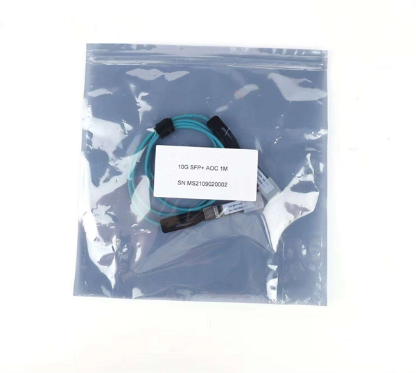
The Fibre Channel physical layer is based on serial connections that use fiber optics to copper between corresponding pluggable modules. The modules may have a single lane, dual lanes or quad lanes that correspond to the SFP, SFP-DD and QSFP form factors. Fibre Channel does not use 8- or 16-lane modules (like CFP8, QSFP-DD, or COBO used in 400GbE) and there are no plans to use these expensive and comple.
[PDF]
Fibre Channel can be used to transport data from storage systems that use solid-state flash memory storage medium by transporting NVMe protocol commands.OverviewFibre Channel (FC) is a high-speed data transfer protocol providing in-order, lossless delivery of raw block data. Fibre. When the technology was originally devised, it ran over optical fiber cables only and, as such, was called "Fiber Channel". Later, the ability to run over copper cabling was added to the specification. In order to avoid confu. Fibre Channel is standardized in the of the International Committee for Information Technology Standards (), an (ANSI)-accredited standards c. Two major characteristics of Fibre Channel networks are in-order delivery and lossless delivery of raw block data. Lossless delivery of raw data block is achieved based on a credit mechanism. There are three major Fibre Channel topologies, describing how a number of are connected together. A port in Fibre Channel terminology is any entity that actively communicates over the network, not necess.
[PDF]
Fibre Channel is standardized in the of the International Committee for Information Technology Standards (), an (ANSI)-accredited standards committee. Fibre Channel started in 1988, with ANSI standard approval in 1994, to merge the benefits of multiple physical layer implementations including, and. Fibre Channel was designed as a to overcome limitations of the SCSI and HIPPI physic.
[PDF]

Download XinZhiZao maintenance software to view the full CLEVO Notebook W230ST Schematic Diagram. The Schematic, Circuit Diagram PDF file for CLEVO Notebook W230ST Laptop Motherboard. Pages: 102, Format: PDF, File Size: 4. Page 5 This manual is intended for service personnel who have completed sufficient training to undertake the maintenance and inspection of personal computers. It is organized to allow you to look up basic information for servicing and/or upgrading components of the W230ST se- ries notebook PC. Page. These drivers or Manuals are customized for CLEVO's Notebook PCs only. We would not advise using them with other vendors' products. If you have any problem about file linking error, please mail to marketing@clevo. tw If can't download a file with IE11, please try with Firefox or Chrome to. My Clevo W230ST 6-7P-W2304-003 motherboard is faulty so I'm searching for the repair & services guide with electronics schematics to see how to fix it. I'd like to measure the different chips voltage so if someone could help me find and download the Clevo W230ST 6-7P-W2304-003 service manual it. We have 29 Asus WSeries W230ST Motherboards / System and laptop parts in stock and available for immediate shipment. Asus W Series W230ST Motherboards / System Replacement Laptop Parts. Battery, Keyboard, Fan. Notebook Clevo W230ST - Service manuals and Schematics, Disassembly / Assembly.
[PDF]
Each type is optimized for specific uses and includes features suitable for different devices. They use precision ferrules and alignment sleeves to connect two fiber cores, maintaining light transmission efficiency. Fiber connector types LC, SC, FC, ST, MTP, and MPO are widely used in past and present. What are the differences between them? Who is the most popular one? Find the answer in the article. What is a Fiber Connector? The optical fiber connector is a kind of detachable passive optical component used. A fiber optic connector is a mechanical device used to align and join optical fibers, enabling light to pass through with minimal loss. This connector landscape reflects how modern SFP deployments prioritize port density and. Fiber optic connectors are the unsung heroes of modern networking. They are small, often overlooked components, yet they are essential for ensuring high-speed, low-loss, and reliable optical transmission. An optical fiber connector enables quicker connection and disconnection than splicing. Because of this, it's no surprise that fiber optic connectors are in high demand.
[PDF]

Use the SWD or JTAG interface to connect the ST-Link v2 to the STM32 microcontroller. Download and install STM32CubeIDE or another compatible IDE. Install the ST-Link USB driver (available on the STMicroelectronics. The ST-LINK/V2 is an in-circuit debugger/programmer for the STM8 and STM32 microcontrollers. The single wire interface module (SWIM) and the JTAG/serial wire debugging (SWD) interfaces facilitate communication with any STM8 or STM32 microcontroller operating on an application board. ATOLLIC, IAR and KEIL Integrated Development Environments for. How do you use SWD (Serial Wire Debug) for debugging STM32? - HackMD Using SWD (Serial Wire Debug) for debugging STM32 microcontrollers is a powerful way to monitor and control code execution, inspect registers, and analyze faults. Here's a step-by-step guide to set up and use SWD effectively: 1. In addition. This small guide will explain how to connect your debugger to your development board. There are two commonly used connectors which expose only the SWD (Serial Wire Debug) interface or the full JTAG interface. If you are using one of ST's official Nucleo or Discovery boards, you do not have to. To upload a program to a chip from Thomson Semiconductor you need an ST-Link programmer device to connect your PC. Thompson sells branded programmers, adaptors and cables. We'll use an inexpensive ST-LinkV2. They look like AVR programmers but you need to read the pinouts on the side.
[PDF]

To properly remove the optical cable: Locate the port > Stabilize the device > Gently grasp & pull the plug (not the cable) straight out > Do the same with the other end > Cover both connectors with plastic tips. To remove the plastic tip: Gently twist and pull off the protective plastic tip from. How To Unplug Optical Audio Cable | How To Remove Optical Cable. For inquiries: tutorialswithterry@gmail. more Sound or visuals were significantly edited or digitally generated. For. Understanding how to remove optical cable is crucial for maintaining the integrity of your audio setup and ensuring a seamless transition between devices. In this guide, we will navigate the intricacies of safely detaching optical cables from various connectors, exploring the proper techniques and. If you have an audio system setup using optical cables, you can easily remove the cables should the need arise for repairs, improvements or replacement. Turn around the first device from which you want to disconnect the optical cable. You should try to get as much access to the cable as possible. In this article, we have provided a step-by-step guide on how to remove a digital optical cable from a TV and also have included some additional tips that you must follow while removing the cable from your TV. So, what are you waiting for? Let's read and remove the cable. Why Does Correctly Remove.
[PDF]
When in inventory, unlocks recipe for Cold Resistant Metal Armor (Legendary). Can be crafted at High Quality Workbench. An Medium Size Plate armor set from King Gragnar in The Warrens. The set consists of only 12 pieces (no back), for a total of 102 AC, +17 Sv Magic and weighing 79. 0) gives a total of. The Channel Armor Ritual allows, once per Logistics Period per charge, a wielder of a Target Staff or Wand to expend Celestial Channeling points equal to the amount of the damaging attack to make the verbal call "Cloak" and take No Effect from an attack where their Base Armor would be taken below. An Medium Size Plate armor set from King Gragnar in The Warrens. 0) gives a total of. Were you looking for Cold Iron Armor? To Royal Guard Sheltuin, you say, 'I wish an audience with the Overlord' Royal Guard Sheltuin says, 'The Overlord is not seeing anyone at this time, however I may have work for you. You seem to have some experience with the Kobold annoyance in the region. Are. monstertrain://challenge/ProductsBalancedCentre 16K subscribers in the MonsterTrain community. A place for all things Monster Train, discussions, suggestions, memes, screenshots.
[PDF]

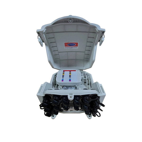
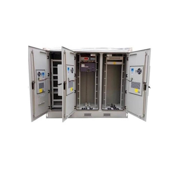
ODN provides the optical transmission channel between OLT and ONU. Each ONU analyzes the signal transmitted from the ODN, extracts the portion intended for that ONU, and schedules user information to send back via the ODN. The Passive Optical Network (PON) is the indispensable foundation for delivering ubiquitous, multi-gigabit broadband connectivity, a necessity for modern economies and residential life. The shift from outdated electrical copper systems to optical fiber is driven by the immutable demands for. PON (passive optical network) is a fiber-optic network that employs a point-to-multipoint topology and fiber optic splitters to transmit data from a single source to multiple user endpoints. In contrast to AON, multiple customers are connected to a single transceiver by means of. A GEPON system usually consists of an OLT (Optical Line Terminal) at the service provider's central office and multiple ONU (Optical Network Units) or ONT (Optical Network Terminals) close to the end user as optical splitters. This network is distinguished by its capability to make the data transmission from a single source to multiple user terminals. While both devices are essential in a Passive Optical Network (PON) setup, they serve entirely different.
[PDF]

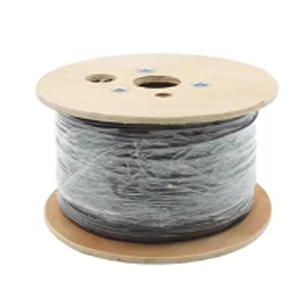
This guide covers everything: what fiber optic pigtails are, how they differ from patch cords, which connector and polish type to specify, how to choose between mechanical and fusion splicing, and the real-world applications where pigtails are the right call. Whether you're building out an ODF. Optimize your cable management with our slotted wall cable routing channel. The slotted design allows for easy access and routing, ensuring secure and efficient installations. They are the bridge between fiber optic cables in the field and the equipment or patch panels that manage them. By combining factory-installed connectors with spliced bare fiber, pigtails ensure that network installers can create. The fiber optic pigtail is a short terminated optical fiber with a connector on one end, used to facilitate easy connections between fiber optic cables and various devices. This article will show you what a fiber optic pigtail is. The success of a network in fiber optic cable installation heavily. The Fiber Optic Pigtail is a foundational component in modern telecommunications, serving as the critical link for terminating fiber optic cables. The connector end plugs into devices like transceivers or patch panels, while the bare end is typically fusion spliced to a fiber optic cable. This setup ensures.
[PDF]