
This handbook covers the code of practice in protection circuitry including standard lead and device numbers, mode of connections at terminal strips, colour codes in multicore cables, dos and donts in execution. Also principles of various protective relays and schemes including special protection. Read this document and the documents listed in the additional resources section about installation, configuration, and operation of this equipment before you install, configure, operate, or maintain this product. Users are required to familiarize themselves with installation and wiring instructions. presentation of protection and control relaying. The report will identify methodology behind these practices, present issues raised by the integration of microprocessor relays and the internal logic and external communication configurations, ying. The objective of this presentation is to convey a basic understanding of protective relays to an audience of engineers already familiar with low voltage protective device coordination. HT panel protection relay. The HT power supply is received from GO switch and distributed to the. The handbook for protection engineers includes guidelines on protective circuitry, protective relay principles, and testing procedures for switchgear and relays. It covers standard codes, wiring practices, and norms for protecting generators, transformers, and lines, and provides detailed.
[PDF]

Precast concrete trench systems provide protection and easy access to power, communication, fiber optic, control, and signal wires and cables. Engineered precast trench is used in the power, utility, and transportation industries and can also be used in conjunction with catch basins, inlets, and. Completing Outside Cable Plant Installation. Underground cables are pulled in conduit that is buried underground, usually 1-1. 2 meters (3-4 feet) deep to reduce the likelihood of accidentally being dug up. In extreme cold climates, cables may need to be buried at greater depths where there. THE SOLID APPROACH TO TRENCHING. Made of a unique, patented. Trenwa is the original manufacturer of precast concrete trench and offers the broadest line of proven trench systems. Trusted by Industry Leaders: Trenwa has been a go-to partner for North American infrastructure projects for over for over 60 years. Request a quote today to see how our products can. Waskey's Precast Cable Trench System offers a durable, customizable solution for protecting and organizing critical infrastructure. If you need any help, be sure to reach out. Precast Concrete Trench for underground utility purposes. Primarily used for enclosure of electrical, communication, power cables, and piping.
[PDF]

Numerical relay are embedded with specialized digital signal processor (DSP) as the computational hardware. By using DSP as the relay's processor, the relay is capable of meeting the fundamental protective requirements such as reliability, sensitivity, selectivity and speed . Thus, various protective devices are used to protect the power system, of which digital signal processor (DSP) numerical relays are capable of significantly improve protection operations. Therefore. Manuals and User Guides for Samwha DSP DSP-VIP-PM Motor Protection. We have 1 Samwha DSP DSP-VIP-PM Motor Protection manual available for free PDF download: Manual Samwha dsp DSP-VIP-PM Motor Protection Pdf User Manuals. View online or download Samwha dsp DSP-VIP-PM Motor Protection Manual. Many of the new protection relays are microprocessor based and are generally referred to as numerical relays. This means that signals from transducers are sampled at fixed time intervals, digitally encoded, and processed by equipment which resembles a computer to derive relaying information, e.
[PDF]
The system that is used to cover busbar protection consists of overcurrent or distance protection. Making use of this system the busbar will be inherently protected. This system also can be used as bac.
[PDF]

Are the protection parameters set correctly (trip value, trip time)? Is the assigned protection function blocked? Is the protection function´s trip signal routed to the Trip-Manager of the correct switchgear? Is the trip signal of the switchgear . Are the protection parameters set correctly (trip value, trip time)? Is the assigned protection function blocked? Is the protection function´s trip signal routed to the Trip-Manager of the correct switchgear? Is the trip signal of the switchgear . Master trip relay or lockout relay, also known by ANSI code 86, holds a significant position as an intermediator between the protection relay and control points, even though it is not self-equipped with fault sensing capabilities. The master trip relay can operate as a hub of multiple protection. Since protection relays can be expensive, it is not advisable to connect them directly to the trip coil. if the fault detected by any of the protection relay means at the same time the protection relay trips the associated circuit breaker through the mater tripping relay circuits. Master trip relay is not a monitoring relay. It. After first start-up of the protective device there is a pending trip. Two red LEDs are illuminated at the front of the HMI. It typically refers to the time duration taken a.
[PDF]
In electric power systems and industrial automation, ANSI Device Numbers can be used to identify equipment and devices in a system such as relays, circuit breakers, or instruments. The device numbers are enumerated in ANSI/IEEE Standard C37.2 Standard for Electrical Power System Device Function Numbers, Acronyms, and Contact Designations. Many of these devices protect electrical. List of device numbers and acronyms• 1 - Master Element• 2 - Time-delay Starting or Closing Relay• 3 - Checking or Interlocking Relay, complete Sequence• 4 - Master Protective. A suffix letter or number may be used with the device number; for example, suffix N is used if the device is connected to a Neutral wire (example: 59N in a relay is used for protection against Neutral Displacement); and suffixe.
[PDF]

Ellen discusses how protective relays work, types of protective relays, and how protective relays are applied in real-world power systems. Understand key ANSI functions, which are essential for designing, operating, and maintaining safe and efficient electrical. Hi friends this channel is all about sharing of my experience in the field of electrical engineering and protection system. Different types of relays used in sub station for different protection purpose. I am trying to share my knowledge and this is. Learn about protective relays, the essential devices used to safeguard electrical power systems from faults and abnormal conditions. We encourage you to post often and enjoy! Is it possible to learn protection relay testing without the hardware? I do all kinds of typical HV testing - AC/VLF hipot, IR, IPF, winding. Omron Electronics P6K Relay Sockets & G6K Low Signal Relays, enabling easy relay replacement to reduce downtime, labor, and overall maintenance costs. Learn everything you need to know about protective.
[PDF]

Product Features: Square protective box, suitable for skin cable and leather cable tight protection 6cm in length of skin heat shrink tube welding protection. A close connection between the leather cable and pigtail. Looking for specific info?. *In the era of high bandwidth, reliable fiber optic power equipment is particularly important. This handheld photometer can help check cable performance, calculate relative power loss, locate faults, and troubleshoot. *Measure the length of network cables, coaxial cables, and telephone cables. Able. Usually ships within 3 to 4 weeks Click here for details of availability. Able to test open, short, cross-connect, See more product details TABKER 4000667180167 3 x 2 x 1. Check each product page for other buying options. Price and other details may vary based on product size and color. Need help?. power across any given fiber. This document will serve as an overview of the major features and functions of the device and will ofer tips for trouble shooting com on issues in optical networks. If you are looking for a low cost device capable of saving and reporting take a look at the RP460 or. ments to the instrument's performance and functionality. The figures given in this manual ion of this manual to ensure the accuracy of its contents. However, should you have any questions or fi gistered users with a variety of information and services. Please allow us to serve you best by.
[PDF]

Selecting the right cable type ensures that the structure itself provides first-level protection. UV-Resistant Jackets (PE or LSZH): Prevent sunlight degradation. Water-Blocking Gel or Tape: Stops moisture migration inside the cable. Metal or Non-Metallic Armoring: Adds crush and. This guide covers how to safeguard outdoor fiber optics across underground, aerial, direct-burial, and exposed setups. Before applying protective measures, it's essential to understand the main risks fiber optic cables face outdoors. UV Exposure: Prolonged sunlight degrades standard plastic. Fiber optic cables are often used for long-distance communication due to their high bandwidth and low signal attenuation. Outdoor fiber optic cables are installed in harsh environments where they are exposed to various environmental factors such as temperature changes, humidity, moisture, dust, and. Optical cable lines lightning protection and strong current protection are achieved by avoiding, guiding or discharging them underground to prevent lightning and strong current from causing damage to the optical cable lines themselves, communication equipment and personnel. Since the lightning. The Fiber Optic Association, Inc. (FOA) was founded in 1995 to help develop the workforce to build the fiber optic networks to support a rapid expansion in communications and the Internet. Introduction: Why Fiber-Optic Cable Damage Matters Fiber-optic cables transmit data via pulses of light.
[PDF]

This guide provides clear cost ranges in USD and practical pricing details for U. Typical cost range for a single relay is $2–$150 depending on type and rating. Buyers typically pay a range for relays, and cost is driven by relay type, coil voltage, contact rating, and packaging. This guide presents practical price estimates in USD, with low–average–high ranges and real-world factors that affect total cost. Assumptions: region, specs, labor hours. Relays. The SEL-351 Protection System has built-in Ethernet and IEEE C37. 118 synchrophasors, and is ideal for directional overcurrent applications. Optional Mirrored Bits communications and power quality monitoring add flexibility to solutions. The SEL-351 is the protection standard for utility and. Buyers typically pay a modest amount for small signal relays and higher sums for industrial or specialty units. The main cost drivers are the relay category (signal, automotive, or industrial), quantity, and installation requirements. Although failure of a protective relay system may have severe local or regional impacts, most protective relay systems are not required to operate to prove they are in working order. Ensuring that. What are Protection Relays and How Do They Work? Protection relays are specialized devices designed to detect abnormal conditions in electrical systems and initiate appropriate actions to protect equipment and personnel. These intelligent sentinels continuously monitor electrical parameters and.
[PDF]
These are single- or multi-conductor control cables designed for use in trays or substations. They feature insulation made from XLPE, EPR, PE, or PE/PVC, and are protected by jackets made of CPE, PVC, or LSZH. Our cables are suitable for various installations, including cable trays, direct burial. Substation Control Cable is a general purpose control cable, which is primarily used in industrial and utility applications, for distribution or control circuits and for the interconnection of operation of protective devises. Substation Control Cable can be installed in open air, in ducts or. Lightera products are used in electrical substation automation applications. Competitively priced and designed for minimal environmental impact, this cabling solution allows for reliable. Abstract:The design, installation, and protection of wire and cable systems in substations are covered in this guide, with the objective of minimizing cable failures and their consequences. These cables are crush resistant, have a high degree of varying temperature ranges (from -50c to +75C), are easy to terminate, and can withstand any environment. Power Cables High Voltage (HV) Cables: Used to transmit.
[PDF]
Thermal relays are the perfect solution for providing protection to motors which provides the most precise tripping for the electric motor during single phasing and overload. This article discusses an overview.
[PDF]
The original unstructured record data for the defect of the relay protection devices (RPDs) may contain problems influencing the data mining, and it is lack of quantitative evaluation. So the purpose of this.
[PDF]
Important transmission lines and generators have cubicles dedicated to protection, with many individual electromechanical devices, or one or two microprocessor relays.OverviewIn, a protective relay is a device designed to trip a when a is detected. The first protective relays were electromagnetic devices, relying on coils operating on moving par. Electromechanical protective relays operate by either, or. Unlike switching type electromechanical with fixed and usually ill-defined operating voltage thresholds.
[PDF]

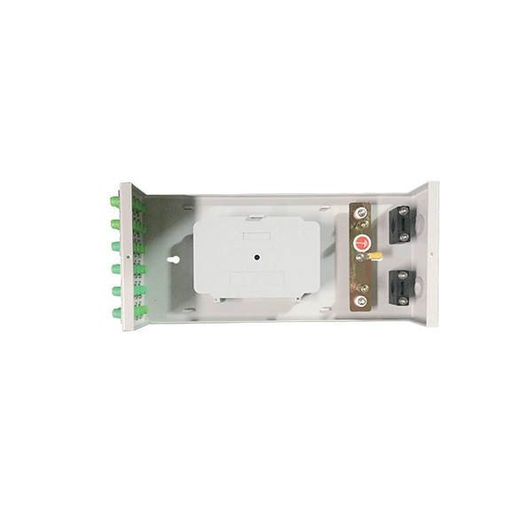
Protect fiber optic cable connections:The joint box provides physical protection for the fiber optic cable connection parts to prevent damage to the fiber optic cable caused by external environmental factors such as moisture, dust, chemical corrosion and mechanical damage. Provide a stable. Fiber optic sleeves are protective devices used for fiber optic connections. Splice protection sleeve, usually made of plastic or metal, are used to secure and protect the fusion joint between two optical fibers. Fiber Cable Joint Box is attributed to the mechanical pressure sealing joint system. Fiber Cable Joint Box is a continuous protection device for supplying optical, sealing and mechanical strength continuity between adjacent optical. The optical fiber terminal box is the terminal joint of an optical cable, one end of which is an optical cable, and the other end is a pigtail, which is equivalent to a device that splits an optical cable into a single optical fiber. The user optical cable terminal box installed on the wall, its. Fiber Optic Splice Closure is designed to protect optical fibers from debris, dirt, dust, moisture and water. As much of the fiber system is outside in a harsh environment, these fiber optic splice closures are designed to meet the tough protection requirements of fiber-optic splices. UnitekFiber. Overview Application of Optical Fiber Splice Closure/Joint Box/Joint Closure: 1. CATV environment.
[PDF]


