More than $69million (USD$30. 51m) will be channeled to Fiji in highly concessional capital via the multinational development partner-funded Climate Investment Fund (CIF) – to transform systems and enable the electricity grid to absorb and channel more clean power. The CIF governing board has. This International Merchandise Trade Statistics provides information on Fiji's exports, re-exports and imports of goods between Fiji and the rest of the world. The administrative data used to compile this release is supplied by the Fiji Revenue and Customs Service (FRCS). The REI Plan which represents a first-of-its-kind effort that will channel.
[PDF]

Towers are not rooted by only pouring concrete—they require extensive soil analysis, wind loads, types of towers, and seismic activity to determine the necessary foundation for safety and sustainable use. A communication tower foundation design is the structural blueprint that determines the anchor point of the tower on the ground. This article delves into the intricate process of civil construction tailored. Tower owners must comply with a multi-layered regulatory, engineering, and safety framework that governs tower siting, where a cell tower can be built, how it must be designed, and how it operates throughout its lifecycle. These requirements ensure public safety, structural integrity, regulatory. Here are six foundation types for communication towers that work for a wide range of situations and environments. If you're planning a new installation, knowing the basics of these foundations can help you establish a secure and durable tower that will be a community asset for years to come. Telecom (Telecommunications) towers are a generic description of radio masts and towers built primarily to hold telecommunications antennas. As such antennas often have a large area and must be precisely pointed out, such towers have to be designed and built to limit wind induced movement. The Contractor shall employ a quality control program that will ensure that engineering, fabrication.
[PDF]
Energy consumption growth of the fifth-generation (5G) mobile network infrastructure can be significant due to the increased traffic demand for a massive number of end-users with increasing traffic volum.
[PDF]
The key lies in their fully sealed design, acting as a “protective shield” for the cabinet, effectively preventing dust, salt spray, and high-temperature air from entering. So, how can this more reliable cooling solution become more economical to support large-scale 5G. ESTEL designs each Telecom Power System and outdoor telecom cabinet to adapt to these challenges. You get reliable performance through robust materials, smart energy management, and advanced engineering. ESTEL's dedication to quality, innovation, and international standards ensures your equipment. With 5G base stations, smart light poles, outdoor communication cabinets and other infrastructures spreading all over urban and rural areas, outdoor telecommunication equipments are facing severe tests such as extreme temperature difference, humidity and rain, and dust intrusion. Traditional. Available in different configurations, Delta OutD cabinets are designed to protect equipment from external threats in all climates from the tropics to the arctic. In addition to traditional cooling methods, Delta's new hybrid cooling options revolutionize the cost structure of thermal management. Featuring a robust steel structure with IP-rated protection, it ensures reliable operation against dust, rain, heat.
[PDF]

Communication networks are an integral part of interconnected transmission lines in a power grid, analogous to the spinal cord for control signal and information exchange among substations, data hubs, and load dispatch centers. This article cov. Communication networks are an integral part of interconnected transmission lines in a power grid, analogous to the spinal cord for control signal and information exchange among substations, data hubs, and load dispatch centers. This article covers the major trend and design aspects of fiber optics communication link in power transmission line netwo. The communication network in the power grid is one of the most interrelated systems that require perfect compliance in equipment and protocol selection. While the high voltage components are relatively unchanged over decades in terms of operating principles, the communication protocols and equipment are seeing astonishing advancements every year. S. 2.1 Knowhow of prevailing setupWhile the primary objective is always to get the best solution for the lowest price, in the case of extension projects, the design engineers must also keep an eye on the existing setup. The issue of back-compatibility and upgradationsshould be properly accessed in existing equipment, even more so in the case of proprietary legacy setups. Figure below illustrates one such group of communication equipment in existing substations that might need proper interfacing and compatibility adapters befo.
[PDF]
1. Scope: This quality procedure is made to enumerate to perform the fiber optic cable installation, termination and testing work in SAOMPP Project. 2. Purpose: The purpose of this quality procedure is to establi.
[PDF]
The data from September 2023 shows that 21 countries have achieved penetration rates higher than 50%. The UAE leads the ranking with 99,3%, while Singapore positions itself second at 97,1%. Hong Kong (95,3%), China (92,9%), and South Korea (91,5%) complete the top 5 positions. This report provides an analysis of Omdia's Fiber Development Index (FDI). The FDI quantifies and ranks the level of investment in fiber optical networks across nine metrics on a country-level basis. This analysis helps industry stakeholders, including policymakers, regulators, service providers. The Mobile Connectivity Index measures the performance of 173 countries against the key enablers of mobile internet adoption. In the European. Global Fiber-optic Cable key players include ZTT, YOFC, Prysmian, HTGD and FiberHome. Global top five manufacturers hold a share about 40%. Asia-Pacific is the largest market, with a share over 60%, followed by North America, with a share about 16 percent. 8 billion by 2029 from USD 3. 4% from 2024 to 2029. Rapid expansion of data centers, cloud services, and 5G infrastructure is driving strong adoption of fiber optic solutions. 80% during the forecast period (2023-2032). This expansion is driven by surging demand for high-bandwidth networks, 5G.
[PDF]

This comprehensive guide will explore the importance and benefits of this integration, provide an understanding of fiber optic cable and Ethernet ports, discuss their compatibility, and offer a step-by-step process for connecting them. Proper connection of fiber optic cables is essential to harness these benefits fully, as even minor errors can lead to significant performance issues like signal loss. This article will guide you through the necessary tools, materials, and methods on how to connect fiber optic cables effectively. Using an optical cable involves connecting it to the right equipment, ensuring proper installation, and testing the system for optimal performance. Here's a step-by-step guide on how to use optical cable effectively: 1. Check Compatibility of Equipment Ensure that your equipment (e., network. One powerful solution to achieve these goals is by connecting fiber optic cables with Ethernet ports. This comprehensive guide combines industry standards with field-tested practices to ensure you achieve a rock-solid. These transceiver modules are hot-swappable input/output (I/O) devices that plug into 100BASE, 1000BASE and 10GBASE ports (for SFP+), which connect the module port with the fiber-optic or copper network. The SFP transceiver modules are hot-pluggable I/O devices that plug into module sockets. The number one cause of signal loss in optical fiber installations is dirt on.
[PDF]

STM-1 (Optical / Electrical), E1 and Ethernet Multi-Service SDH Transmission Unit is a modular platform unit with two 155. 52Mbps optical / electrical interfaces, which may be used in a point-to-point, chain or ring application to provide an ultra-compact, cost effective and flexible. STM-1 Mux is a cost-effective, compact (only 1U high), SDH (Synchronous Digital Hierarchy) multiplexer that is designed for applications in metro and access networks for efficient transport of traditional TDM and emerging data traffic. It provides 63 E1 TDM interfaces in only 1U standard 19". The LentronicsTM TN1U SDH Multiplxer delivers powerful optical networking solutions for critical communications applications. With a wide range of tributary interface units, the TN1U provides both transport and access capabilities for voice, data, IP/Ethernet Wide Area Network (WAN), video and. Valiant's offers STM-1 63 E1 (Optical / Electrical), Add-Drop SDH Multiplexer unit is a modular platform unit with two 155. R-STM-1E can be deployed in access nodes as a terminal multiplexer (TM) or an add & drop multiplexer (ADM). It enables expansion of the local loop up to 100 km / 62 miles. Note: 1643 AM STM-1 (Aggregate and tributary) or STM-4 optical access is via an SC-type connector. Adaptors FC and ST are also supplied. 1643 AMS: All optical interfaces are available as SFPs (Small Form-Factor Pluggable Optics) for STM-1 transmission only. Note that the 1643 AM supports S1.
[PDF]

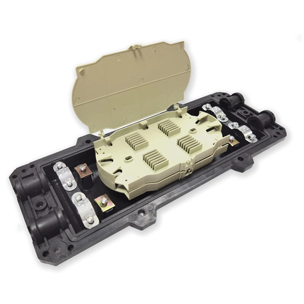
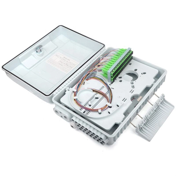
The terminal box provides: Strain relief: Cable clamps and grommets transfer tensile loads from fiber to chassis, preventing microbends and fiber breakage. Bend-radius control: Internal routing with ≥30 mm radius (typical for G. A2/B3 bend-insensitive fibers) minimizes induced attenuation. Slack. A Fiber Access Terminal (FAT), also known as a Fiber Access Terminal Box (ATB) or Fiber Distribution Terminal (FDT), is a key component found in optimized fiber optic access networks for FTTH implementations. It is a small enclosure that can house and protect the fiber optic cables, splices, and connectors. The fiber termination box. GAO Tek's fiber terminal boxes are devices used in fiber optic networks to terminate and manage fiber optic cables. Our boxes serve as a connection point for incoming and outgoing cables, providing cable termination, organization, and protection. GAO's box includes features such as cable. Fiber optic terminal box is a product use for different scenarios in FTTH construction, such as primary or secondary splitting. People usually use it to connect patch cables from the splitter to the indoor cables, meeting the demands for high-speed bandwidth services. It is widely used in optical fiber communication systems, such as Fiber to the Home (FTTH), Local.
[PDF]

Dispersion of an optical fiber directly affects the bandwidth and distance capability of the fiber optic link and reduces its efficiency. The higher the dispersion, the lower the potential data rate and transmission distance. Fiber optic cable transmission distance is determined by two primary physical factors that affect signal quality as light travels through the fiber medium. The greater the distance, the greater. With amplifiers, such as Erbium-doped fiber amplifiers (EDFAs), the distance can be extended to 600 miles or more, and even further with additional amplifiers for long-haul applications. In this guide, we'll explore how fiber optic cables function, the maximum distances for different types of fiber optics, and tips for. Fiber optics transmits information by sending light signals through thin strands of glass. While this technology offers higher speeds and longer distances than traditional copper wiring, physical limitations impose distance constraints. Light pulses degrade as they travel over long spans, primarily. The maximum distance a fiber optic cable can transmit data reliably is influenced by several key factors, primarily the inherent properties of light and the physical characteristics of the fiber itself. Understanding these limitations is essential for designing efficient and robust internet.
[PDF]
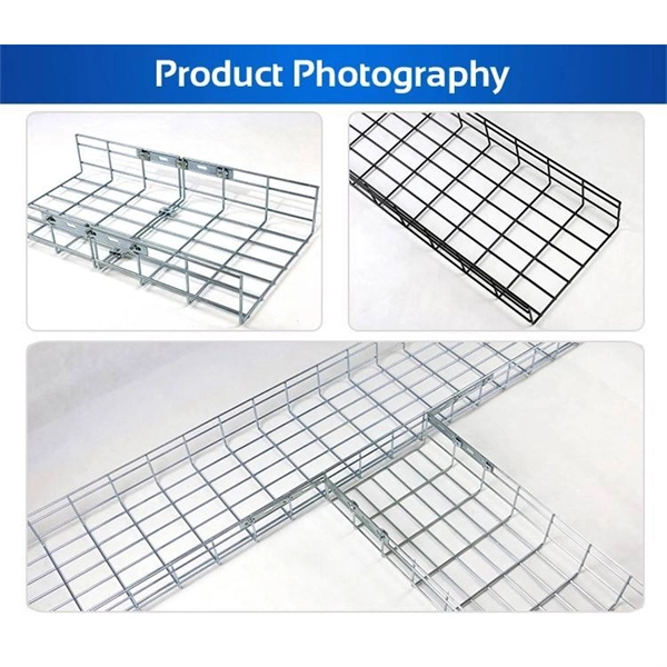
This guide provides a comprehensive engineering perspective on ODFs—beyond the basic “what is an ODF” explanation—covering structural design, fiber management, MPO/MTP integration, and selection criteria for modern high-density deployments. Why ODFs are the Foundation of. This complete guide explores everything you need to know about ODFs — from their structure, types, and key components, to installation best practices and modern design trends. Whether you're building a central office, data center, or FTTx distribution network, understanding the right ODF. In the complex architecture of fiber optic networks, the Optical Distribution Frame (ODF) serves as the linchpin for organizing, protecting, and distributing optical signals. As data centers, enterprises, telecom operators, and smart-building infrastructures deploy increasingly dense fiber links, ODFs provide the structured. An ODF is a central hub in fiber optic networks, crucial for managing and organizing the variety of fiber-optic cables and connections entering a facility such as a telco central office (CO). They provide efficient fiber optic management, connectivity, and protection. What is Optical Distribution Frame An Optical Distribution Frame (ODF) is the central hub of your fiber optic network.
[PDF]

The FLS-140 is the easiest way to identify optical fibers from end to end and locate polished connector endfaces. Its red laser shines through most yellow-jacketed optical fibers to help you pinpoint breaks, bends, faulty connectors, splices and other causes of signal loss. A Visible Fault Identifier (VFI), also referred to as a Visual Fault Locator (VFL), is an essential tool for fiber installation and maintenance technicians. AFL's compact VFI4 injects high-powered red-laser light to provide exceptional brightness and range for locating defects in single-mode and. The B5 Rechargeable Red Light Pen is a professional 650nm visual fault locator designed for fiber optic network maintenance, installation, and troubleshooting. Its advanced rotary automatic lift laser head ensures smooth operation, while the integrated LED lighting improves visibility in low-light. Whether installing or troubleshooting, the Visual Fault Locator (VFL) is an essential tool that quickly and easily locates problem areas in fiber cables. By pinpointing the exact location of fiber damage, technicians can diagnose, troubleshoot, and fix the problem efficiently. The VFL is also used. The state, throughput, and identification of an optical fiber can be easily checked with fiber testers by coupling highly visible laser light into the optical fiber. A high intensity visible red laser beam is precision-coupled.
[PDF]

The procedures in this document describe basic inspection techniques and processes of cleaning for fiber optic cables, bulkheads, and adapters used in fiber optic connections. Note: This document is intended for use by service personnel, field service technicians, and. There are three main principles that needs to be taken in consideration for an efficient optical connection: a perfect core alignment, perfect physical contact and dirt-free connectors. It is important that every fiber connector be inspected and cleaned prior to mating. That advice is misguided. It could hurt an installer or get them sued by an irate network owner. This guide outlines best practices for maintaining and inspecting installed fiber optic infrastructure, enabling network owners to keep their systems running at peak efficiency. Fiber optics infrastructure consists of optical fiber cables, connectors, splice enclosures, distribution panels, and. Small oil micro-deposits and dust particles on fiber optic cable optical surfaces may cause a loss of light or degraded signal power which may ultimately cause intermittent problems in the optical connection. Fiber optic testing and maintenance protocols not only maintain the reliability of the network, but also allow for early detection of potential failures and optimization of performance.
[PDF]

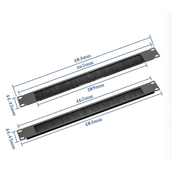
In this guide, you will learn how to interpret network diagrams like a pro, from symbols and scope to segmentation, dependencies, troubleshooting, and security clues. A rack elevation diagram is a visual representation of the equipment and components contained within a rack in a data center or server room. It provides a clear overview of the physical layout of the rack, including the placement and positioning of servers, switches, storage devices, and other. Learn how to read and interpret network diagrams effectively to troubleshoot, validate security, and plan network changes with confidence. Have you ever opened a network diagram and felt like you were staring at a subway map with no station names? That is a common problem, even for experienced IT. Network cabinet cabling describes the structured connection and arrangement of all IT components in a server rack. The aim is a secure, maintainable and scalable operation of the network environment. The amount. A standard operating procedure, or SOP, is a set of step-by-step instructions compiled by an organization to help workers carry out complex routine operations. Work instructions should be very detailed on "how" to accomplish a specific job, task or assignment. It helps teams understand network architecture, data flow, and dependencies, making it easier to design infrastructure, troubleshoot issues, and plan.
[PDF]