
Generator protection relays are devices that detect abnormal operating conditions and isolate the generator from the system to prevent damage. These relays act as the first line of defense and are installed with strict adherence to IEC Standard for Protection Relays. Protecting generators from different electrical, mechanical, and thermal stresses is known as generator protection. To safeguard machines from overloads and unusual circumstances, preventive measures are required. Faults are inevitable even with effective design, construction, and operation. Below is an overview of the different types of relays used in generator systems, their functions, and their specific applications. Electromagnetic relays use. Generator Protections are broadly classified into three types: Class A, B and C. Class A covers all electrical protections for faults within the generating unit in which generator field breaker, generator breaker and turbine should be tripped. What Are Generator Protection Relays? Generator protection. There are various protection relays and those are used for protection against a wide variety of conditions. The fundamental principles that are covered in this course are equally applicable to. IEEE C37. 2 defines the IEEE “numerical” function designation for all protective relay functions. This presentation primarily uses the designations from the Beckwith M-3425A relay, which in most cases follows IEEE C37.
[PDF]

This guide provides clear cost ranges in USD and practical pricing details for U. Typical cost range for a single relay is $2–$150 depending on type and rating. Buyers typically pay a range for relays, and cost is driven by relay type, coil voltage, contact rating, and packaging. This guide presents practical price estimates in USD, with low–average–high ranges and real-world factors that affect total cost. Assumptions: region, specs, labor hours. Relays. The SEL-351 Protection System has built-in Ethernet and IEEE C37. 118 synchrophasors, and is ideal for directional overcurrent applications. Optional Mirrored Bits communications and power quality monitoring add flexibility to solutions. The SEL-351 is the protection standard for utility and. Buyers typically pay a modest amount for small signal relays and higher sums for industrial or specialty units. The main cost drivers are the relay category (signal, automotive, or industrial), quantity, and installation requirements. Although failure of a protective relay system may have severe local or regional impacts, most protective relay systems are not required to operate to prove they are in working order. Ensuring that. What are Protection Relays and How Do They Work? Protection relays are specialized devices designed to detect abnormal conditions in electrical systems and initiate appropriate actions to protect equipment and personnel. These intelligent sentinels continuously monitor electrical parameters and.
[PDF]

Here's a step-by-step guide to help you properly arrange fiber optic patch panels in a data center environment. Before installation, assess your network's current and future needs:. This guide outlines the key steps and considerations for effective cable management in fiber optic systems. Managing fiber optic patch cables requires strict adherence to technical standards due to the unique material properties of the cables. Even the most advanced optical transceivers can only perform at their peak when paired with properly installed, clean, and precisely managed fiber. Knowing the ins and outs on fiber patch cords and how they are important in server racks Glass fiber patch cords are very slim cables that are excellent at transmitting information quickly and in great quantity. It is essential when racks of servers are used, to maintain a strong and secure. In this configuration, a permanent link is installed between QuickNetTM Patch Panels in the switch/network cabinet and the server or storage cabinets. The most common, flexible, and upgradeable QuickNetTM Fiber Solution is shown in Figure 2, below: In this configuration, permanent links are. Patching fiber optic cable involves carefully splicing two ends together to repair a break or extend a cable run. Here's a breakdown of the process: Assess the Damage and Prepare: Carefully inspect the damage to determine if a patch is feasible. Severely damaged cables may require replacement.
[PDF]
FREE delivery September 9 - October 1. Details See more product details Generic MLS-2C917F4515D9256DC4F47693141D3C0C MLS-2C917F4515D9256DC4F47693141D3C0C 40a Would you like to tell us about a lower price? Found a lower price? Let us know. Nanjing Antu Elevator Accessories Co. is a professional company that operates various elevator accessory brands, including light curtains, insoles/rails, fans, Yimeike power supplies, elevator switches/keys, emergency power supplies, steel wire ropes, communication boards, etc. Since its. Elevator Disconnect, Power Module Switch, 200 Amp, 480 Volt AC, NEMA 1 Enclosure, 120 Volt AC Coil, Key Test Switch, Green Pilot Light, 2 Normally Open/Normally Closed Auxiliary Contacts, 3 Pole Fire Alarm Voltage Monitoring Relay Category: 3-Pole 480 Volt Elevator Disconnect Switches Elevator. FREE delivery September 9 - October 1. From everyday maintenance to urgent repairs, our extensive inventory, quick shipping, and knowledgeable support team help you get the job done—safely, reliably, and without. Eaton's simple and economical elevator control fusible disconnect switch is an all-in-one solution that meets NFPA, NEC and local building codes related to hydraulic elevator applications. Additionally, it includes a shunt trip disconnect, relays to receive FACP signal and monitor shunt trip.
[PDF]

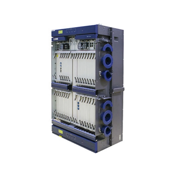
This handbook covers the code of practice in protection circuitry including standard lead and device numbers, mode of connections at terminal strips, colour codes in multicore cables, dos and donts in execution. Also principles of various protective relays and schemes including special protection. Read this document and the documents listed in the additional resources section about installation, configuration, and operation of this equipment before you install, configure, operate, or maintain this product. Users are required to familiarize themselves with installation and wiring instructions. presentation of protection and control relaying. The report will identify methodology behind these practices, present issues raised by the integration of microprocessor relays and the internal logic and external communication configurations, ying. The objective of this presentation is to convey a basic understanding of protective relays to an audience of engineers already familiar with low voltage protective device coordination. HT panel protection relay. The HT power supply is received from GO switch and distributed to the. The handbook for protection engineers includes guidelines on protective circuitry, protective relay principles, and testing procedures for switchgear and relays. It covers standard codes, wiring practices, and norms for protecting generators, transformers, and lines, and provides detailed.
[PDF]
Thermal relays are the perfect solution for providing protection to motors which provides the most precise tripping for the electric motor during single phasing and overload. This article discusses an overview.
[PDF]
The original unstructured record data for the defect of the relay protection devices (RPDs) may contain problems influencing the data mining, and it is lack of quantitative evaluation. So the purpose of this.
[PDF]
Important transmission lines and generators have cubicles dedicated to protection, with many individual electromechanical devices, or one or two microprocessor relays.OverviewIn, a protective relay is a device designed to trip a when a is detected. The first protective relays were electromagnetic devices, relying on coils operating on moving par. Electromechanical protective relays operate by either, or. Unlike switching type electromechanical with fixed and usually ill-defined operating voltage thresholds.
[PDF]
In electric power systems and industrial automation, ANSI Device Numbers can be used to identify equipment and devices in a system such as relays, circuit breakers, or instruments. The device numbers are enumerated in ANSI/IEEE Standard C37.2 Standard for Electrical Power System Device Function Numbers, Acronyms, and Contact Designations. Many of these devices protect electrical. List of device numbers and acronyms• 1 - Master Element• 2 - Time-delay Starting or Closing Relay• 3 - Checking or Interlocking Relay, complete Sequence• 4 - Master Protective. A suffix letter or number may be used with the device number; for example, suffix N is used if the device is connected to a Neutral wire (example: 59N in a relay is used for protection against Neutral Displacement); and suffixe.
[PDF]

87N high-impedance protection requires special class × current transformer cores with equal transformation ratios. The 7SJ60 relay can alternatively be connected in series with the 7UT613 relay to save this CT core. Earth faults on the secondary side are detected by current relay 51N. However, it has to be time-graded against downstream feeder protection relays. Primary circuit-breaker and relay may be replaced by fuses. Go back to contents ↑. Relay 7UT612provides numerical ratio and vector group adaptation. Matching transformers as used with traditional relays are therefore no longer applicable. Line CTs are to be connected to separate stabilizing inputs of the differential relay 87T in order to ensure stability in the event of line through-fault currents. Relay 7UT613provides numerical ratio and vector group adaptation. Go back to contents ↑. The directional functions 67 and 67N do not apply for cases where the transformers are equipped with the transformer differential relays 87T. Go back to contents ↑.
[PDF]

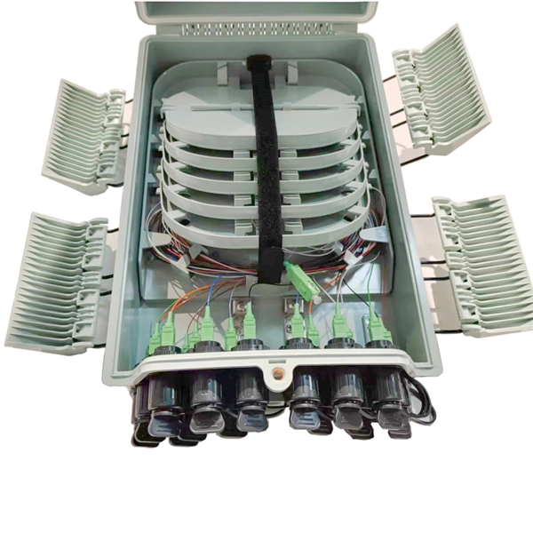
The LC optical fiber pigtail is designed with a push-pull mechanism, enabling easy installation and removal without compromising on performance. Executive Summary: A fiber optic pigtail is one of the most commonly specified yet least understood components in structured cabling. Get the wrong connector type, the wrong polish, or skip proper fusion splicing technique—and you're looking at elevated signal loss, increased back reflection, and a. Fiber pigtails are simple in appearance, yet essential in function. They are the bridge between fiber optic cables in the field and the equipment or patch panels that manage them. By combining factory-installed connectors with spliced bare fiber, pigtails ensure that network installers can create. Fiber optic network design refers to the specialized processes leading to a successful installation and operation of a fiber optic network. It includes first determining the type of communication system (s) which will be carried over the network, the geographic layout (premises, campus, outside. All Rights Reserved. fCONSTRUCTION QUALITY REQUIREMENTS FOR FTTP & SSP Work Orders This document provides Construction Technicians, Construction Managers, FTTP/SSP Vendors, and Inspectors with the essential information to ensure a quality build and to successfully pass an Outside Plant Inspection. These terminations must be of the right style, installed in a.
[PDF]
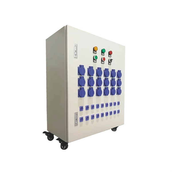
We manufacture and supply high-quality meter boxes and distribution boards for residential, commercial, and industrial applications. Our products are made from durable materials and designed to meet safety standards and regulations. We also offer custom solutions to meet. Electrical installation works require a very good planning design and safe execution. In order to ensure that the installation complies with the Zimbabwean standards and that the installation works efficiently, it is worth entrusting the electrical installation works to experienced professionals. We supply solar products, electrical products for industrial and domestic installations and we are experts in Solar system installations. We do fault findings for both solar system. We. Specialized electrical engineering contractors serving Zimbabwe & Southern Africa. From design to commissioning, we deliver comprehensive. LAIWO offers a full range of distribution boards and consumer units including metal consumer units, EV garage units, TP&N distribution boards, plastic enclosures and MCB metal boxes. All units come. The Distribution Box serves as the load centre and distributor of electrical power. A distribution box ensures that electrical supply is distributed in the building, also known as a Distribution Board, Panel Board, Breaker Panel, or Electric Panel. It is the central electrical supply system of any.
[PDF]
🏃♂️�� Grenada Intercol 2023 – Boys Open 4x400m Relay Watch the thrilling relay action from the 2023 Republic Bank Inter‑Secondary Schools Athletic Championships (INTERCOL) held at the Kirani James Athletics Stadium in St. more 🏃♂️🔥 Grenada Intercol 2023 – Boys Open 4x400m Relay. Our Relay Services provides the full range of services such as: TTY, Voice Carry Over (VCO), two-line Voice Carry Over (2LVCO), Hearing Carry Over (HCO), Speech-to-Speech (STS), Visually Assisted Speech-to-Speech (VA STS), ASCII, Voice, Enhanced Voice Carryover (Captioned Telephone or CapTel), and. No description has been added to this video. Audio tracks for some languages were automatically generated. Learn more Enjoy the videos and music you love, upload original content, and share it all with friends, family, and the world on YouTube. CARIFTA GAMES GRENADA 2026 | GIRLS 4x400M RELAY U17 FINAL | DAY 3 Until This Happened 😱 No description has been added to this video.
[PDF]
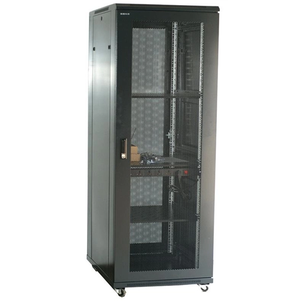
A comprehensive four-layer physical security strategy is the best approach to keeping vital network infrastructure secure. Specialized safeguards like locked cabinets, fire suppression systems, and precise climate control are essential to protect critical network equipment from. Working in a computer room can involve special fire protection issues; electrical, ventilation, security, and work practice issues also apply. Computer rooms (or “data centers”) have an increased risk of fire, because of the electrical energy used to run the machines, the heat generated by. Physical and environmental security controls are implemented to protect the facility housing system resources, the system resources themselves, and the facilities used to support their operation. The term physical and environmental security, as used in this chapter, refers to measures taken to. After determining physical security needs and assessing current physical risks, take the appropriate steps to secure the environment. This allows for one control to remain in place if another one fails. For example, you might. The checklist below outlines seven essential steps to safeguard your equipment, data, and business continuity. Control Access to the Server Room Restricting entry to authorised personnel is one of the most effective ways to reduce physical security risks.
[PDF]
You might have bad connections or lose signal if you bend them too much. Rough handling can also cause problems. Clean them often and manage them with care to stop these issues. If you act early, you will have less downtime. Your network will work better and stay smooth. Proper installation and regular maintenance of fiber optic patch cords play a crucial role in achieving optimized network performance, preventing signal errors, and extending service life. This guide addresses expert-certified best practices applied by professionals in the telecommunications, data. Patching operations must follow principles of neatness, aesthetic cabling, ease of operation, and minimal space usage within ODF frames, optical cross-connects, and integrated boxes. Patch cable lengths should be controlled with a surplus of no more than 500mm. Never use patch cables that are too. Effective fibre optic cable management is crucial for ensuring network reliability, performance, and long-term efficiency. Poorly routed cables, inadequate strain relief, and excessive bending can result in signal loss, increased maintenance, and costly downtime. Incorrect cable lengths can lead to signal attenuation, which refers to the loss of signal strength as it travels through the cable. Plan your fiber patch cord.
[PDF]


