
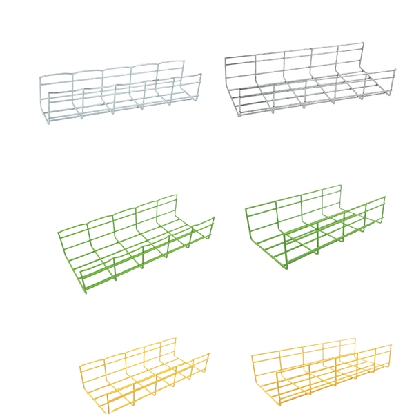
Cable Trays* — Max two 24 in. (610 mm) wide by max 6 in. (151 mm) deep open-ladder cable tray with channel-shaped side rails formed of 0. 54 mm) thick aluminum or min 0. In practice, cable tray dimensions are a system of interrelated measurements —width, depth, length, and material thickness—that directly affect cable fill compliance, heat dissipation, structural loading, and long-term expandability. From an engineering standpoint, cable tray dimensions are not. Perforated Cable Tray System expertly constructed from high-grade stainless steel, offering exceptional durability and resistance to corrosion. With side height 100mm. A properly designed and installed cable tray system will provide. Studs — Wall framing to consist of wood studs or channel shaped steel studs. Wood studs to consist of nom 2 by 4 in. Additional studs shall be used to completely frame. Best Size: Here, deep trays (75mm to 150mm) are used since power cables are typically thick and heavy. Data cables, such as your Wi-Fi or computer ones, are extremely sensitive. They do not get hot; however, they do not like to hang or sag. In case a data cable folds in an excessive manner, the. ect the minimum bend ra-dius for cables as they exit the bottom of the cable tray. A rung spacing of 6 to 9 inches (150 to 230 mm) is preferable when the cable tray cont d for instrumentation and control applications that require additional protec eferred to support and protect numerous small.
[PDF]

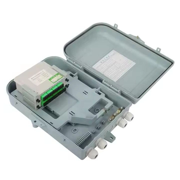
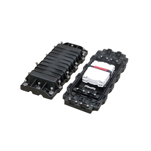
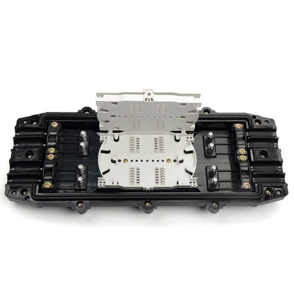
Installing a fiber optic splice closure efficiently and effectively requires attention to detail and adherence to specific procedures. Here's a structured guide to ensure optimal installation, protecting the integrity of your fiber optic network connections. comIn this channel you will find fiber optic telecommucation products like fiber optic cable, jumpers, fibe. along wall corners, skirting boards, door and window frames—places that are visually discreet. Avoid areas prone to damage or high temperatures. Clean the wall surface or skirting boards along the planned route thoroughly to remove dust, grease, or moisture that could affect adhesion. If necessary. In this guide, we cover the basics of fiber optic splicing, how to perform splicing using two different methods, and finally some best practices to perform good fiber splicing. What is Fiber Optic Splicing and Why is it Needed? – #1. Use and Maintain Your. The Ultimate Guide to Fiber Optic Splice Closure: Importance, Types, Installation and Maintenance Fiber optic splice closure plays a crucial role in the installation and maintenance of fiber optic networks. Components in the Fiber Optic Splice Closure A) The closure includes the items shown below plus additional cable attachment hardware. The cover is a cylindrical plastic enclosure with corrosion resistant metal hardware.
[PDF]

IEC 60793-1-40:2019 is available as IEC 60793-1-40:2019 RLV which contains the International Standard and its Redline version, showing all changes of the technical content compared to the previous edition. IEC 60793-1-40:2019 establishes uniform requirements for measuring the. All Rights Reserved. fCONSTRUCTION QUALITY REQUIREMENTS FOR FTTP & SSP Work Orders This document provides Construction Technicians, Construction Managers, FTTP/SSP Vendors, and Inspectors with the essential information to ensure a quality build and to successfully pass an Outside Plant Inspection. Four methods are described for measuring attenuation, one being that for modelling spectral attenuation: -method D:. The first ITU-T Handbook related to optical fibres, Optical Fibres for Telecommunications, was published in 1984, and several others have been produced over the years. This Standard may also apply to the Jet Propulsion Laboratory other contractors, grant recipients, or parties to agreements PR 8735. 2, Hardware Quality Assurance Program Requirements for Programs and Projects. Use. Note: This list was assembled from a number of sources with various dates - we doubt it is complete because they change all the time. A full catalog of TIA specs is at org/ Learning More About Standards and Codes There are a number of ways of finding out more about cabling.
[PDF]
Fusion splicing is most widely used as it provides for the lowest loss and least reflectance, as well as providing the most reliable joint. Virtually all singlemode splices are fusion. 📦 For purchasing, use the RP Photonics Buyer's Guide for fiber cleavers. It provides an expert-curated supplier directory, buyer-focused technical background information, and structured selection criteria to support professional procurement decisions. In many applications of fiber optics, it is. The fiber optic quick connector/cold connector is a very innovative field-terminated connector, which contains factory-installed optical fiber, pre-polished ceramic ferrule and a mechanical splicing mechanism. The incoming optical fiber or indoor optical fiber can be inserted into the mechanical. A reliable fiber-optic network depends on more than selecting the right cable and connectors; it hinges on the quality of every splice. In fact the splice shall ensure high quality and stability of performance with time. Either joining method must have three primary characteristics. Fiber joints are the points where two optical fibers are permanently connected to create an uninterrupted transmission path. These connections are essential in fiber optic networks, enabling the extension, branching, or repair of fiber cables while ensuring minimal signal loss during transmission.
[PDF]
If a surge protector shows signs of failure, act quickly. Follow these steps: Turn off the main power before touching the device. Take out the failed surge protector from the system. This keeps protection against lightning surge and overvoltage. A surge protector is an electrical device designed to protect electronic equipment from voltage spikes, surges, and other power-related issues. It works by absorbing or diverting the excess energy away from the connected devices, thereby preventing damage. A typical surge protector consists of. The ground wire is the primary mechanism for clearing these ground faults and protecting occupants. Testing the surge protector in a different three-slot outlet confirms whether the device is. An AC Surge Protector keeps important electronics safe from lightning surges and high voltage. You should check the status window often and do simple maintenance. This helps the device work well. You can look for signs of damage. Make sure the. Want to save money and extend the life of your surge protectors? In this video, I'll show you how to easily repair a blown surge protector after a power surge. You don't need to keep buying new ones! Learn how to identify a damaged Metal Oxide Varistor (MOV), replace it with simple tools, a. If the Protected light is off or red or you hear a replace alarm or the unit is old or low joule replace it. When in doubt replace rather than rely on a multimeter reading.
[PDF]
This guide dives deep into the most prevalent fiber optic network problems, their root causes, and actionable solutions. Fiber optic technology is essential for modern communication, offering unparalleled speed, reliability, and efficiency. However, improper installation can lead to severe performance issues, expensive repairs, and unnecessary downtime. To ensure a high-functioning fiber optic network, avoid these. Understanding the common causes of failure and implementing preventive measures is essential to maintaining reliable networks and avoiding costly downtime. In this article, we explore the primary modes of field failure in fiber optic cables and outline best practices to prevent them. This article outlines three key errors and how to avoid them.
[PDF]
The correct fix would be to land every neutral in its own terminal first, then combine EGCs as necessary to connect to the remaining holes. Example: join all #14s into one or two #14s, all #12's into one or two #12s, everything larger gets its own terminal. Exactamundo, with the same. Join ABR Electric's exclusive Residential Appliance Installer License (R. ) course in McKinney, TX, and elevate your career with expert-led training. Limited to just 5 spots, this course covers everything from NEC Codebook navigation to test-taking strategies, ensuring you're fully pre. more. A pigtail wire is a short cable used to lengthen short wires. Also, it can join several wires to become a single conductor for electrical connections. They also come in handy to lengthen circuit wires that are too short to reach a device. The National Electrical. How to Make Electrical Pigtails: This is a basic tutorial on what electrical pigtails are and how to make them. Disclaimer: Always use multiple sources and do your homework before performing any electrical work. Also, make sure all work is done within national and local code. As an electrician, I have to pigtail ground wires every once in a while and can say it's pretty easy once you get the hang of it. Below I will provide straightforward.
[PDF]
Click Systems tab Electrical panel Cable Tray. From the Type Selector, select the cable tray type, with or without fittings. On the Options Bar, specify the width, height, offset, or bend radius. more. I am preparing Cable Tray Drawing where i need to provide Cable tray tags on each tray. for that I have Modified default tray Tag family as per my requirement. I use “Comment” Parameter to to tag my cable trays. in my Model there are many Trays and it is very much lengthy and time consuming task. Understand how to model a cable tray using the systems tab in the electrical section for effective coordination, especially in the electrical room. Learn how to set the middle elevation, draw through the room, avoid conflicting elements, and create a detailed and clear visualization of the cable. Sized for the cable fill of the runs it carries. Above lights, below ducts — coordinate with ceiling plenum. Tees, crosses, and reducers handle every direction change. Noble Desktop's Revit MEP Certification Course covers Revit fundamentals — a strong foundation before specializing in mechanical. Join this channel to get access to perks: This lesson walks through how to start a project and properly set up for Electrical Cable Tray design in Revit 2025. It focuses on template selection, component availability, and basic setup steps. Start With the Right Template Opens a new project and.
[PDF]

The fastest way to test a fluorescent tube is with a multimeter set to continuity mode. Each end of the tube has two pins connected by a thin filament inside the glass. If either filament is broken, the tube is dead. The whole test takes about 30 seconds per tube once you know what. This is a complete guide for testing a fluorescent light bulb with a multimeter. You don't have to be an expert in electrical work. This process measures electrical resistance to determine if the tube has suffered an internal failure before replacing the bulb or investigating the ballast. This guide provides a comprehensive understanding of the process, equipping you with the knowledge and. To test a fluorescent light bulb, observe any of the following: flickering light, low brightness, buzzing sound, delayed start, and fading color and light variation. Turn off the power to the circuit that powers the fixture and keep the leads steady to ensure accurate readings. Multimeters provide. How to Test Light Bulbs & Fluorescent Tubes with a Multimeter (Continuity Check) Is your lamp or fixture failing to light up? Before you buy a new bulb, you need to confirm if the bulb or tube itself is the problem! A simple continuity check using a multimeter can instantly tell you if the filament.
[PDF]
They can weigh between 60 to 200 kg per kilometer (39. 7 to 132 pounds per 1000 feet), depending on the design and materials used. The weight of fiber optic cables can vary widely based on the factors mentioned above. However, some general guidelines can provide a rough estimate: Indoor Fiber Optic Cables: These are typically lighter as they require less protection. Indoor cables can weigh anywhere from 10 to 30 kg per. Fiber per Tube *: No of tube(13-24) shall be with black tracer but black* tube(20) with white tracer. Fiber per Tube *: Tube identification with one black stripe. In case of Black tube with white marking. This cable is perfect for headend termination to a fiber backbone, termination of fiber rack systems, multi-floor deployment where select fibers are used at each floor, or intra-building backbones. It is suitable for all indoor applications where fiber optic cabling is needed. Lighter materials reduce overall cable weight 3. Strength and. CommScope all dry outside plant stranded loose tube cables deliver the same proven quality and performance offered in all CommScope cabling solutions. The construction features the use of dry. The Cisco ® family of QSFP-DD modules provide the industry's highest bandwidth density while leveraging the backward compatibility to lower-speed QSFP pluggable modules and cables. The Cisco 400GBASE Quad Small Form-Factor Pluggable Double Density (QSFP-DD) portfolio offers customers a wide variety.
[PDF]

The number of optical cores in an optical fiber is the total number of equipment interfaces multiplied by 2, plus 10% to 20% of the spare quantity, and if the communication mode of the equipment has serial communication and equipment multiplexing, you can reduce the number of cores. A fiber optic cable typically has multiple cores, depending on its design and purpose. The most common type of fiber optic cable used in telecommunications is single-mode fiber, which usually has a single core. This post will guide you through understanding fiber optic cores and selecting the perfect cable for your needs. Understanding Fiber Cores: Core: The central glass fiber that transmits light signals. Single-mode: A. The total number of cores for a 1pc fiber patch cable is calculated as the number of branches multiplied by the number of cores per branch (if there are no branches, the number of branches = 1). The number of. This guide walks you through the simple decision steps engineers use, the common strand counts on the market, and clear rules-of-thumb for different project types so you choose a cable that fits both today's needs and tomorrow's growth. Begin by listing what the network must support now and in five. Fiber optic cables are used to transmit data and audio signals using light. They come in different types, each designed for specific applications and distances.
[PDF]

This article helps network engineers, field techs, and IT managers choose the right single-mode transceiver campus optics by tying IEEE Ethernet requirements to day-to-day deployment constraints: reach, budgets, DOM behavior, and operational limits. Huawei eKit offers a comprehensive series of pluggable optical modules in the Huawei eKit portfolio. The wide variety of modules gives you flexible and plug-and-play options for all types of interfaces. You will also get a practical checklist, common. Multimode and Singlemode optical modules differ in terms of fiber type, transmission distance, cost, and application scenarios. Understanding these differences is the first step in selecting the right module. This saves space and money. Dual fiber modules use two fibers. They are easier to set up and give steady communication. Its primary function entails converting electrical signals into optical signals. This assembly comprises a light source, such as a laser diode or a semiconductor light-emitting diode (LED), an optical interface, a. A single-mode receiver is an optical device that converts incoming light signals—carried over single-mode fiber (SMF)—back into electrical data. Unlike multimode receivers, which accept wider light beams from LEDs or VCSELs, single-mode receivers pair exclusively with laser-based transmitters.
[PDF]

show interface - To view the configured IP address on the switch. These are the various commands referenced in this document: Updated Grammar and Formatting. Finding the IP address of your network switch is crucial for a variety of tasks, from configuring its settings to troubleshooting network connectivity issues. While it might seem like a technical hurdle, several straightforward methods can help you uncover this essential piece of information. This article provides a comprehensive guide to locating the IP address of a Cisco switch, covering various methods and tools available to network administrators and. Knowing the IP address of your switch is essential for network troubleshooting, configuration, and management. However, finding the IP address of a switch can sometimes be challenging, especially if you don't have access to its documentation or network infrastructure details. In this article, we. This guide will go over how to find the IP address of the M4300 & M4250 and how to access the web interface of the switch. Check the DHCP server to find the new lease from the switch. VLAN 1 default IP address. Two of them are Cisco ones the third one is a D-Link. My predecessor was managing them, unfortunately, when I inherited them I got zero information about it and. Configure the IP address on the switch. Do the next steps to set the system parameters on Catalyst switches that run Cisco IOS software. For details on how to connect to the Console ports of the.
[PDF]
The Total Cost of Ownership (TCO) for Passive Optical LAN (POL) is often wrongly seen as high. Meanwhile, Optical LAN can be cheaper in rip & replace use cases, even in brownfield scenarios. Moreover, the long-term return is significant. Hardware and deployment. Often the lower costs are a result of Passive Optical LAN (POL) ability to: The Association for Passive Optical LAN (APOLAN) Technology Committee members recently completed a POL cost comparison study. They did so by analyzing the cost of POL parameters (e. 4-port PoE ONTs, ONTs shared in. The elimination of costly IDFs is one of many capex-reducing elements that users enjoy when they switch to POL, finds recently released cost comparison produced by the Association for Passive Optical LAN (APOLAN). There are no IDFs at this high-end. Passive Optical LAN replaces copper and multi-tier switches with fiber-optic cabling and passive optical splitters based on FTTH GPON/XPON technology. POL transforms a LAN into a simple and flat fiber cabling network. POL covers large building projects and long-distance transmission without the. The Association for Passive Optical LAN (APOLAN) announced the results of it Passive Optical LAN Cost Comparison study, conducted to illustrate the possible economic advantages of POL over traditional enterprise networks based on Category cable.
[PDF]

This is the most fundamental ring topology, formed by connecting three or more switches in a closed loop using fiber optic cables. Data can flow in either direction, allowing the network to recover quickly if a link fails. If you have multiple Ethernet switches that need to be connected over long distances, fiber is obviously a preferred choice. Moreover, when it comes to bandwidth, no currently available technology is better than single-mode fiber. It can provide significantly higher bandwidth and carry more data. A single 6 strand fiber can only connect 3 switches back to the core. How many switches do you plan to connect? A star is great for a limited number of switches. I have maybe 20 coming back to my cores. Rings are generally not done anymore, but I think that is for bandwidth as much as anything else. The mainline of the fiber optic LAN directly connects to the switch, then to the router. The connection between two or more Ethernet switches in a certain way (Uplink port, etc. ) is called the cascade. All switches have two fiber ports. Is the best way to have fiber backbone switch and connect fiber channel from every switch to the backbone? Or connect switch 1 to switch 2 to switch 3 to. switch 12 to switch 1 again? Thanks! Let's get some. I need to connect 4 Floor Building with 4 Cisco 2960 - 48 ports switch each other and it needs to be through a fiber. This design ensures data can travel in both directions.
[PDF]
