
A beamsplitter is a common optical component that partially transmits and partially reflects an incident light beam, usually in unequal proportions. In addition to the task of dividing light, beamsplitters can be employed to recombine two separate light beams or images into a single. Beamsplitters are fundamental components in optical engineering, serving to precisely divide a single input beam of light into two distinct output beams. This division allows for the simultaneous analysis or utilization of the light's properties along two separate paths. It is a crucial part of many optical experimental and measurement systems, such as interferometers, also finding widespread application in fibre optic telecommunications. a laser beam) into two (or sometimes more) beams, which may or may not have the same optical power (radiant flux). Different types of beam splitters exist, as described in the. The beam splitter splits and then recombines infrared radiation, while the detector picks up the resulting signal. It's sensitive to both intensity and frequency. Together, they decide just how accurately an instrument captures those unique infrared “fingerprints” from different substances.
[PDF]

Optical fiber technology has revolutionized the way we communicate, enabling fast and reliable data transmission over long distances. In this article, we will explore the different types of optical fibers used in communication systems and their applications. Fiber Optics or Optical Fiber is a technology that transmits data as a light pulse along a glass or plastic fiber. An Optical Fiber is a cylindrical fiber of glass that is hair-thin in size or any transparent dielectric medium. The fiber which is used for optical communication is waveguides made of. Optical fibers are the backbone of modern communication. They transmit light signals over long distances with minimal loss. Let's break down their classification in a simple and engaging way: 1. The less signal damage metal wires can cause, the better for optical fiber connection. Total internal reflection (critical angle, using Snell's law). Higher bandwidth (extremely high data transfer rate). Less signal degradation. Less costly per meter. Lighter and thinner then copper wire. The light is a form of carrier wave that is modulated to carry information. The cladding's refractive index is slightly smaller than that of the core, which confines light within the core and propagates by repeated total reflection at the boundary with the.
[PDF]

PDH called Parallel Data Highway, is a quasi-synchronous transmission technology based on digital transmission. PDH defines multiple multiplexing levels, such as 2Mbps (E1), 8Mbps (E1). This page defines various terms related to the optical domain. It covers SDH, PDH, SONET, DWDM, FTTH, WDM, PDMA, wavelength converters, optical ADMs, EDFAs, and SOAs. Converts optical light from one wavelength to another. Definitions of common terms related to fibre optics, including SDH, PDH. Part I. SDH is a synchronous TDM technology that multiplexes low-order signals into high-order signals. Because the entire network is. PDH (Plesiochronous Digital Hierarchy), is an early digital transmission standard to handle the transport of digital signals over copper and fiber-optic networks. It appeared in the 1980s and developed rapidly. PDH, in the form of traditional point-to-point connection of various media. The term "plesiochronous" refers to the fact that PDH operates with nearly synchronized timing between. The method was developed to replace the plesiochronous digital hierarchy (PDH) system for transporting large amounts of telephone calls and data traffic over the same fiber without the problems of synchronization. SONET and SDH, which are essentially the same, were originally designed to transport.
[PDF]

It consists of 5 buttons. A power button, a button to turn on the VFL, a lambda button to set the wavelendth, a REF button, and a dBm/W button to set the unit of power. First, you check the initial power of a light signal. Then you check its power at the other end of optical. OPM interface: insert the fiber to be tested, test the optical power. REF/dB key: Short press the dB to switch unit, click once nW/dBm/dB to enter the upper clear data, press and hold until REF is displayed on the screen, and set the current optical power as reference value, enter the relative. There are two buttons on this meter. One is the power button, used to turn the meter on/off. At the top, there is a sensor that detects the light beam. The. at -22 (or 25 with tone on)). To do this you. Active Equipment Power Measurement Fiber Continuity Patch Cable Testing Check MM Reference Cables - Dual OWL MM Sources Check MM Reference Cables - WaveSource MM Sources Check SM Reference Cables - Laser OWL SM Sources Check SM Reference Cables - WaveSource SM Sources. Power-off: Press and hold “MODE” key for 2 seconds or more until “OFF” displays on the screen. Note: This instrument will shut down automatically without receiving any operation instruction for 10 minutes. Function selections: It.
[PDF]
LC pigtails are short fiber optic cables which have one connector on their one end and a bare fiber on the other. The connector type most commonly used is the LC connector, known for its compact size and ease of use. It is usually suitable for field termination using a mechanical or fusion splicer. Compared with quick termination or epoxy and polish connections placed on the field. The optical fiber connector is a kind of detachable passive optical component used in the connection between fiber to fiber, the light source to the fiber, and fiber to the detector to achieve the light maximize coupling to the receiving fiber. According to the estimating, there are hundreds of. HOLIGHT fiber pigtails ensure low-loss termination. Available in SC, LC, FC, ST, singlemode & multimode for precise splicing. LC pigtails come in simplex (single fiber) or duplex (two fibers) configurations. Executive Summary: A fiber optic pigtail is one of the most commonly specified yet least understood components in structured cabling. Get the wrong connector type, the wrong polish, or skip proper fusion splicing technique—and you're looking at elevated signal loss, increased back reflection, and a. Fiber optic pigtail has an optical connector pre-installed on one end and a length of exposed fiber at the other end. LC series pigtail normally comes with 0. 9mm cable diameter, UPC/PC and APC versions, SM, MM, OM3 and OM4 modes. 5 meter, also can be as customer's.
[PDF]
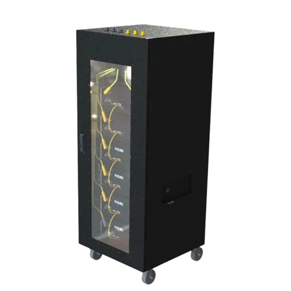
This guide breaks down everything you need to know about electrical distribution boxes in plain English. We'll explain what they are, the different panel types you'll encounter, NEC 408 requirements that govern their installation, and common applications for each type. The power distribution boxes deliver electricity from the main electrical main to other circuits. Several distribution boxes are designed for specific use in offices or industries. Main Distribution Board (MDB) 2. Each. Distribution boxes, also known as electrical distribution boards or panels, are pivotal components in electrical systems, ensuring the safe and organized distribution of electrical power throughout residential, commercial, and industrial environments. It receives power from the main electrical supply and divides it into separate circuits, each. Electrical control panels and distribution boxes are the backbone of modern electrical systems. From powering homes and industrial facilities to supporting medium-voltage infrastructure, these enclosures ensure safe, efficient, and reliable power distribution. Whether it's a small electrical.
[PDF]