GIGALIGHT 800G QSFP-DD SR8 is a hot-pluggable optical transceiver module designed for 800G SR8 Ethernet links in data centers. It adopts 100G PAM4 and VCSEL technology and can realize 800G data exchange within 100m. 800G OSFP/QSFP-DD | Transceiver Modules - FS FS United StatesFREE SHIPPING on Orders Over US$79 Contact Us United States / $ USD All Products Solutions Services Resources Contact Us FREE SHIPPING on Orders Over US$79 United States Home Optical Transceivers Ethernet/RoCE Networking 800G. Cisco QSFP-DD and OSFP 800G ZR/ZR+ digital coherent optics modules enable 800G traffic over amplified Dense Wavelength-Division Multiplexing (DWDM) links up to 120 km for 800ZR and over 1000 km for 800G ZR+. Cisco ® QSFP-DD and OSFP 800G ZR/ZR+ coherent optics modules enable 800G traffic over. Your request has been submitted successfully. Our sales manager will contact you soon. High-density 800G OSFP and QSFP-DD transceivers support InfiniBand and RoCE, enabling 100m to 2km transmission via MMF and SMF. Have any questions? Talk with us directly using LiveChat. It is compatible with most switches(CISCO, Juniper, Arista,Brocade,H3C,HPE, DELL, etc) OSFP 800G SR8 is an Eight-Channel, Parallel, Pluggable, Fiber-Optic OSFP for 800Gigabit.
[PDF]

Continuous-wave operation (cw operation): The laser is continuously pumped and emits light continuously, either on a single resonator mode (→ single-frequency operation) or on multiple modes (see also: single-mode operation). How do optical. EML stands for Externally Modulated Laser (corrected from "External Modulated Laser"). Its basic principle is to supply a constant current to the laser diode, ensuring the LD emits continuous, stable light. An external electro-absorption modulator (EAM) then adjusts light transmittance to generate. A wavelength swept light source emits laser light with a continuously sweeping wavelength. It is suitable for shape measurement and displacement measurement utilizing OFDR (Optical Frequency Domain Reflectometry), an optical sensing method using the coherence of laser light. The transmitting interface inputs electrical signals of a certain bit rate, which are then processed by internal driver chips. Subsequently, the driver semiconductor laser. Industry pundits have recently speculated that demand for 100G/400G switches may take off in 2019, prompting optical transceiver module vendors to sample data center switches with high data transmission rates earlier than expected. As data center operators accelerate upgrades in preparation for 5G.
[PDF]

Bit Error Rate (BER) is a critical performance metric in optical communications that measures the number of errors occurring in a transmitted data stream over a certain period. It is defined as the ratio of the number of bits received in error to the total number of bits transmitted. This ratio is most often expressed using scientific notation (e., 10⁻⁸. USI has industry-leading capabilities in high-speed signal integrity and power integrity (SI/PI) design, as well as advanced thermal simulation and optical simulation using Zemax. In addition, we have strong expertise in high-speed PCB design utilizing mSAP and substrate PCB technologies. USI also. Unlock AI-driven, actionable R&D insights for your next breakthrough. As optical links are increasingly used for high-speed data. Even a digital data transmission system is not totally error-free — statistical fluctuations related to noise influences cause a small percentage of the transmitted bits to be corrupted. The average fraction of incorrectly transmitted bits is called the bit error rate. Offers precise, cost-efficient optoelectronic signal and anomaly testing for high-speed transceivers. · Use control board and replaceable.
[PDF]

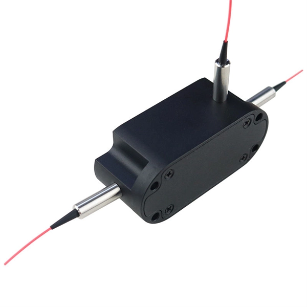
As illustrated in typical SFP internal structure diagrams, the module's core components include an optical transmitter assembly (TOSA), laser driver, optical receiver assembly (ROSA)—some high-sensitivity modules (like L16. 2) use APD receivers, which require an additional booster. The optical module serves as a crucial component in optical fiber communication systems, operating at the physical layer, which is the lowest layer in the OSI model. Its primary function is to achieve optoelectronic conversion by converting electrical signals into optical signals and vice versa. Among various optical module form factors, SFP (Small Form-Factor Pluggable). The function of the optical module is to carry out the photoelectric and electro-optic conversion. In this article, ETU-LINK will introduce to you what are the core components of the optical module? 1. TOSA: Its main function is to convert electrical signals to optical. the embodiments of the present applicationprovide an optical emission module, an emission device, a detection device and a terminal, which can improve the energy density of a light spot formed by an emission light beam and improve the integration of the device. an embodiment of the present.
[PDF]

Optical Modules are hot swappable, and you do not need to power off the device when replacing Optical Modules. Optical Modules are electrostatic-sensitive components. In most enterprise networking environments, the ability to replace hardware without shutting down equipment is essential for maintaining uptime. Do not insert an optical module reversely. Gently pull the module latch or release ring, depending on the module design. Remove the module in a straight motion – do not twist or pull at an angle. Reapply the. Before you begin removing a transceiver from the router, ensure that you have taken the necessary precautions for safe handling of lasers (see Laser and LED Safety Guidelines and Warnings). Ensure that you have the following parts and tools available: The transceivers for the router are. An optical module implements optical-electrical conversion, enabling optical transmission between a DRH and other devices. Disconnecting the optical fibers interrupts the transmission of CPRI signals.
[PDF]

Run the following command to view detailed optical module information on the device interface: display transceiver interface <interface-type> <interface-number> verbose The command output is divided into two parts:. Run the following command to view detailed optical module information on the device interface: display transceiver interface <interface-type> <interface-number> verbose The command output is divided into two parts:. When the optical module on an interface is faulty, you can run the display commands to view information about the optical module. Related Information Video Identify a Huawei-Certified Optical Module Run the display transceiver [ interface interface-type interface-number | slot slot-id ] [ verbose ]. During use, reading optical module information helps understand its real-time operating status, enabling faster troubleshooting of link abnormalities. The following uses the Moduletek SFP-10G-LR module connected to a Huawei S6700 switch as an example to introduce how to read information of the. See the interface module via the optical display command information, including general information of the optical module, manufacturing information, and alarm information. If it is not a Huawei-certified optical module, replace it with a Huawei-certified optical module. If the optical module is installed on a GE port, run the display interfaceGigabitEthernet x/x/x command to view port information when the optical module.
[PDF]
If your high beams are not working, the most likely cause is a blown fuse or a burned-out bulb — both of which you can check yourself in under 15 minutes. That said, there are seven possible culprits, ranging from simple fixes you can handle at home to electrical faults that need a mechanic's. To be clear, I am not saying the highbeams are turning on and off, I mean the actual intellibeam system as indicated by the headlight symbol with the "A" in it on the DIC. When the system is on, the highbeams most of the time will work 100% as expected activating and deactivating when appropriate. Automatic high beam (AHB) systems, sometimes marketed under proprietary names like IntelliBeam or SmartBeam, are designed to enhance nighttime visibility by automatically switching between high and low beams. These systems use forward-facing cameras or sensors to detect light sources from oncoming. Affiliate programs and affiliations include, but are not limited to, the eBay Partner Network. 2021+ Ford F150 Discussion of the 14th generation F150. LED headlight High Beam Failure noticed that high beam on the drivers side LED headlight stopped working. Hooked up the reader and found fault code. Auto High Beam is a safety feature that controls the headlight operation and lights up the road in front using low and high beams. There is too much lag time for enabling the high beams. I just use the old skool manual headlights mode and switch my high beams as.
[PDF]

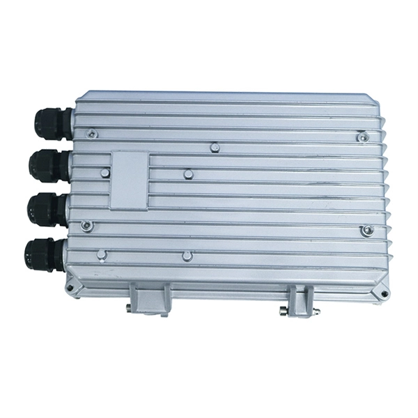
Usually, the 10G/25G grey light optical modules with a short transmission distance are applied for connecting AAU/DU with WDM/OTN/SPN. The connections between WDM/OTN/SPN network devices can be achieved by 10G/25G/50G/100G dual-fiber or single-fiber bidirectional. Compared with Draft A (2013-07-30), this issue includes the following new topic: 2. This section describes engineering specifications of an AAU, including input power and equipment specifications. 7. In 2/3/4G networks, 10Gbps optical modules are generally enough for CPRI interfaces. In 5G networks, CPRI is also upgraded to eCPRI. Currently, 5G of the bearer network mainly uses 25Gbps optical modules. Next, ETU-LINK will introduce the types of optical modules used by 10G SFP+ and 25G SFP28. What is the difference between the 5G bearer network and the traditional optical transmission network? The main difference is that 5G fronthaul needs to support CPRI/eCPRI protocol. Most of the AAU of 5G base stations are deployed outdoors. In order to resist harsh environments such as high. The optical modules used to connect BBU and RRU devices are optical modules and optical fibers. Product Versions The following table lists the product versions related to this document. 25G SFP optical module adopts the wavelength of 850nm, with an operating.
[PDF]

In this tutorial, I will show you how you can connect the Optocoupler to Arduino, read the data as Analog or Digital, and if necessary convert the analog values to digital, and how to reduce noise from the sensor. The Infrared Slotted Optical Optocoupler Module is a device that uses infrared light to transmit signals between two electrically isolated circuits. It consists of an infrared emitter (LED) and a photodetector (phototransistor) housed in a slotted enclosure. When an object passes through the slot. Slotted Optocouplers (Photo Interrupters) are very useful sensors, often included in Arduino projects to detect position of moving objects, measure speed of rotation, or linear motion, frequency of events, and many others. They are easy to use, but it is important to understand how they work, so. This tutorial is a comprehensive, practical guide to the Speed Sensor / Tacho Sensor (Slot-Type Optocoupler) (Leobot Product #245). Moreover, a simple application is programmed that shows how to wire and how to program an Arduino when working with the module. In this tutorial, the module is used as an “digital input board”. If you want to use the. In this project, I will talk about Phototransistor Optical Interrupter Switches (Opto Coupler) Module, how this module works and helps in determining the speed of a rotating object and finally I will show you how to Interface Optical Interrupter Switch Sensor with Arduino and measure the speed of a.
[PDF]

In the photopic region, luminous efficacy peaks at 683 lumens per watt at 555 nm. In fact, the lumen is defined in terms of the power at 555 nm (frequency of 540 × 1012 Hz). Luminous efficacy is defined as the luminous flux produced per unit of power, usually electrical power, measured in lumen per watt (lm/W). It is explained how the overall efficacy of a lighting installation is often lower than that of the light source itself due to factors like light absorption in. Luminous efficacy is a measure of how efficiently a light source produces visible light. Depending on context, the power can be either the radiant flux of the source's output, or it can. The relative spectral responsivity of the human visual system was first defined by the Commission Internationale de l'Éclairage (CIE, the International Commission on Illumination) in 1924. The response of the eye as a function of frequency is called the luminous efficacy of the eye. It has been tabulated for both the light-adapted (photopic) case and the dark-adapted (scotopic) case. Source: Table 6-1 of.
[PDF]

These networks rely on optical fibers, which are thin strands of glass or plastic that carry light signals. The ONU serves as the termination point of a fiber-optic network, converting the optical signals back into electrical signals for distribution to end-user devices. A GEPON system usually consists of an OLT (Optical Line Terminal) at the service provider's central office and multiple ONU (Optical Network Units) or ONT (Optical Network Terminals) close to the end user as optical splitters. In addition, the transmission between OLT and ONU/ONT adopts an optical. In the realm of Fiber-to-the-Home (FTTH) and other FTTx architectures, the Optical Network Unit (ONU) is a critical piece of customer-premises equipment (CPE). The primary function of an. ONU stands for Optical Network Unit. Think of it as. ONU (Optical Network Unit) plays a crucial role in modern telecommunications, enabling seamless connectivity and high-speed data transmission across fiber optic networks. As global demand for Fiber-to-the-Home (FTTH) expands, ONUs have become essential for delivering reliable broadband to homes. As an essential node in Passive Optical Networks (PON), the ONU not only handles the conversion between optical and electrical signals but also supports various services such as data, IPTV, and voice. This article will provide a detailed explanation of the working principles of ONUs and their.
[PDF]
The CFP, short for C form-factor pluggable, is a multi-source agreement to define the form-factor of the optical transceiver for high-speed digital signal transmission. CFP transceivers are defined by CFP MSA to enable 40 Gb/s, 100 Gb/s and 400 Gb/s applications. The c stands for the Latin letter C used to express the number 100 (centum), since. What is a CFP optical module? Is it still relevant in 2026? And when should you choose it over newer alternatives? This guide is designed to answer those questions with clarity and technical depth. In this comprehensive article, we will delve into the world of CFP optical transceiver modules, exploring their. What is CFP Modules? Complete Guide to Standards, Variants, Comparisons, and Applications What is CFP Modules? Complete Guide to Standards, Variants, Comparisons, and Applications What is CFP Modules? Complete Guide to Standards, Variants, Comparisons, and Applications In the era of cloud. This article breaks down the key differences between CFP, CFP2, CFP4, and CFP8 optical transceivers commonly used in fiber optic networks. Figure 1: Dimensions of CFP, CFP2, CFP4, and CFP8 The table below summarizes the specifications of each form factor: 24 W (Max. ) In essence, the progression.
[PDF]

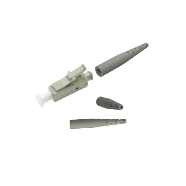
This installation note provides the installation instructions for the Cisco small form-factor pluggable (SFP) and SFP+ transceiver modules. This document is intended to serve as a guide for architecting and deploying fiber optic networks in a customer environment. These transceiver modules are hot-swappable input/output (I/O) devices that plug into 100BASE, 1000BASE and 10GBASE ports (for SFP+), which connect the module. This manual provides safety and installation instructions for the 9490-OS Fiber Optic Passive Splitters. All units use type LC connectors and vary only in the splitting fan-out, and as single or dual-channel capability as listed below. Optical fibers require special care during installation to ensure reliable operation. Installation guidelines regarding minimum bend. Listings and approvals under Time Recorder Co. are the property of Tyco Fire Protection Products. Description Multiple Signal Fiber Optic Modems combine multiple system communications signals and convert them to fiber optic communications for transmission. This guide will focus on the 1x9 dual SC optical transceiver products. Pin Assignment & Description TD+, TD: DC coupled LVPECL inputs for the transmitter.
[PDF]
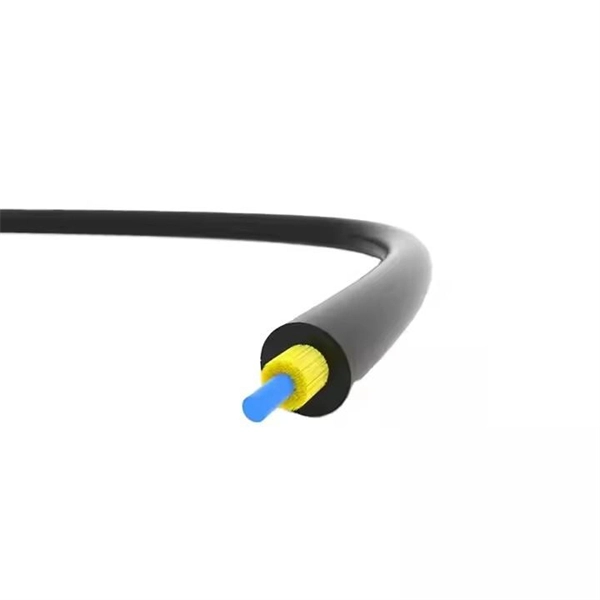
It is designed to transmit data in one direction only. The single-mode optical fiber is designed and engineered to carry one single light mode in a minimal core diameter. It is specified as the best for especially long-distance applications than multimode fiber. Higher-order modes like LP 11, LP 20 etc. Modes are the possible solutions of the Helmholtz equation for waves, which is obtained by combining. Simplex fibers are most commonly used in applications that only require data transmission in one direction. Digital data readouts, interstate sensor relays, and automatic speed and boundary sensors (for sports applications) are all important uses for simplex fiber optic cables. It is designed to. Simplex single-mode fiber is typically used in scenarios where data only needs to be sent in one direction, such as in sensor application like a fire alarm system that sends signals from detectors to a control panel might use simplex fiber. Duplex single-mode fiber is commonly used everywhere else. Single fiber modules (BiDi) use one fiber for both transmitting and receiving data. This saves space and money. Dual fiber modules use two fibers.
[PDF]

A wiring diagram for a photocell and timeclock controller provides a step-by-step guide for installing and connecting all the components in a light system. It shows exactly how each component fits into the overall scheme of things, as well as what wires to use and which connections to. Intelligent Lighting Controls' wiring diagrams show detailed schematics of our solutions. A lighting control module is the “control center” for your lighting system. It acts as a bridge between your physical lighting fixtures and the smart systems that manage them. Instead of relying solely on traditional wall switches, you can control your lights via remotes, mobile or web apps. This guide will discuss the steps needed to integrate with URC Total Control. Commission CSI Controllers Step 2. Locate/Download latest TCM files/Module Step 3. Network Setup Step 6. Supports DALI V2 compatible switches and sensors, works out of the box. Simple and easy setup. ControlByWeb® IoT controllers are a great fit for lighting control in edge applications. Understanding the components that make up a modern lighting system, and how they relate to one another is key to ensuring the best performance and.
[PDF]