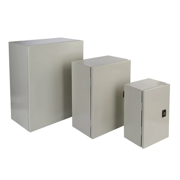
The following tutorial explains how to wire a 120V single-phase breaker and load points in a residential panel. 120V single-phase circuits are commonly used in homes for lighting and receptacle outlets. Plastic is lighter and good for indoor setups. Choose based on where you'll install the box. Inside the box, you'll find things like circuit breakers, busbars, terminal blocks, and wires. These parts control and distribute the electricity to different circuits safely. Some boxes also include DIN. The electrical service panel, often called a breaker box, acts as the central distribution point for all electricity entering a home. Whether you are an electrical contractor or a construction brigade, knowing how to properly and safely install distribution boxes is the basis of ensuring the safe operation of the entire system. This article details the process of installing them, which helps you comprehend distribution boxes. No description has been added to this video. Enjoy the videos and music you love, upload original content, and share it all with friends, family, and the world on YouTube. Jesse Kuhlman is a Master Electrician and the Owner of Kuhlman Electric based in Massachusetts. Jesse specializes in all aspects of home and residential wiring, troubleshooting, generator installation, and WiFi thermostats. Jesse is also the author of four eBooks on home wiring including.
[PDF]

In the following tutorial, we will show how to wire 120V single-phase and 240V split-phase circuit breakers and loads inside a residential main panel. The figure below shows a typical breaker panel used for 120V and 240V circuits. Messy distribution boxes are dangerous and very hard to fix. You will learn to build a safe, efficient, and professional electrical system today. Circuit breaker wiring configurations involve organizing main switches, busbars. A breaker box, also known as a circuit breaker panel, is an essential component of any electrical system. It is responsible for distributing electricity throughout a building, ensuring that each circuit receives the proper amount of power. To understand how a breaker box works, it is helpful to. Each circuit is protected by a circuit breaker, a safety device that automatically shuts off power if it detects an overload or a fault. If you're looking to replace an old fuse box replacement or upgrade your home's power capacity, you'll be dealing with the load center or service panel. The distinction between 1P and 2P circuit breakers plays a pivotal role in determining the appropriate protection level for various circuits. When installing or troubleshooting a power distribution system, understanding how to correctly connect the main electrical supply to the control panel is crucial.
[PDF]

It can occur due to overloaded circuits, short circuits, or ground faults. Solution: Identify the Cause: Check if the breaker is tripping due to overloading. This often happens when too many devices are plugged into one circuit. Reducing the load on the circuit or redistributing. It's shutting off power because something on that circuit isn't safe. The tripping is a warning signal, not a malfunction. But what's causing it? And more importantly, does it need an expensive fix, or is this something simple? The good news: Most circuit breaker trips have straightforward. The main circuit breaker is designed to protect the electrical system in a building or home from overload and potential fire hazards. There are several reasons why a main circuit. A breaker box acts as the central hub that receives electricity from the utility company and distributes it to various circuits in your home. Homeowners will want to hire an electrician to determine the cause of the frequently tripping circuit breaker. When they start tripping, overheating, or making strange noises, it's more than just an inconvenience - it's your home's cry for help. In this guide, we'll walk through these. If you notice that your circuit breakers are often tripping, don't worry. It's a typical issue. Below, you'll find reasons why this occurs and tips to avoid it moving forward. Get a handle on your circuit breaker problems! Circuit breakers are protection devices for electrical circuits.
[PDF]

This comprehensive guide explores the technical requirements, installation best practices, and protection coordination strategies for MCCB-busbar connections. Messy distribution boxes are dangerous and very hard to fix. This guide shows you how to organize circuit breaker wiring properly. You will learn to build a safe, efficient, and professional electrical system today. Circuit breaker wiring configurations involve organizing main switches, busbars. An electrical panel box, also known as a breaker box or a distribution board, is a crucial component of any electrical system. It serves as a central hub for distributing electricity throughout a building, ensuring that power is delivered safely and efficiently to all the required locations. The distinction between 1P and 2P circuit breakers plays a pivotal role in determining the appropriate protection level for various circuits. Wiring Square D Panel refers to the process of connecting electrical circuits within a Square D panel, which is a type of electrical panel commonly used in residential and commercial buildings. The electrical panel, also known as a distribution board or breaker box, is responsible for distributing. While some homeowners may attempt this, it's highly recommended to hire a qualified, licensed electrician for circuit breaker box wiring. This is a complex and potentially dangerous task that involves working with high voltage electricity. To understand how a breaker box works, it is helpful to.
[PDF]

This guide shows you how to organize circuit breaker wiring properly. You will learn to build a safe, efficient, and professional electrical system today. Circuit breaker wiring configurations involve organizing main switches, busbars, and branch breakers within a distribution box. Messy distribution boxes are dangerous and very hard to fix. You lower the chance of circuits getting too hot or overloaded when you pick the right box for your needs. When installing or troubleshooting a power distribution system, understanding how to correctly connect the main electrical supply to the control panel is crucial. Professional electrical panel schedule tool for creating detailed load distributions, calculating circuit loads, balancing phases, and ensuring NEC compliance for electrical distribution panels. Panel schedules are essential for electrical system documentation, load analysis, and NEC compliance. Material preparation: Prepare the required circuit breakers, wires, wiring ties and other materials, and ensure that they meet the design drawings and installation requirements. Location determination: Determine the installation position of the circuit breaker according to the position of the. Hey, in this article we are going to see the Single Phase Distribution Box Wiring Diagram and Connection Procedure. And all the switching and protective devices are installed in the.
[PDF]

What is the main cause of attenuation in fiber? Attenuation in fiber mostly happens from absorption and scattering. The fiber material takes in some light as it moves. Both of these things make the signal weaker as it goes through the. Optical Signal Attenuation is the single greatest factor limiting the distance and performance of your network. Understanding it is crucial for anyone involved in data centers, telecommunications, or enterprise networking. This guide will demystify signal loss, explore its causes, and show you how. Optical fibers are a key component in modern communication systems, carrying signals over long distances. However, even the most advanced optical fiber suffers from attenuation, which is the loss of signal power as it travels along the fiber. Understanding the causes of signal loss and implementing mitigation strategies is essential for maintaining network efficiency. From infrastructure planners to telecom engineers. Optical fiber technology enables rapid data transmission over vast distances by guiding light signals through thin strands of glass. Losses can be introduced by various means such as intrinsic material absorption, scattering, bending, connector loss and more.
[PDF]

First, inspect the optical module appearance for physical damage, cracks, missing components, poor solder joints, or burn marks. Next, compare voltage, resistance, and waveform parameters between a normal it and the suspected faulty one, both in powered and unpowered states. As core components of optical communication systems, the proper installation and use of optical modules directly impacts network stability. This article systematically identifies common anomalies during optical module installation. However, during installation and daily operation, various issues may arise. The following will introduce the causes of various problems and how to deal with them. Optical module method/step 1. During the test, the value of the module I BiasADC is 0, and the TXLOP-ADC and. These compact devices convert electrical signals to optical signals and vice versa, enabling data transmission over fiber optic cables. While generally reliable, failures do occur, leading to frustrating downtime, performance degradation, and costly troubleshooting. This comprehensive guide details. Have you ever dealt with sudden network drops from faulty optical modules? Issues like this cannot only break communications, but they can really jeopardize business continuity.
[PDF]
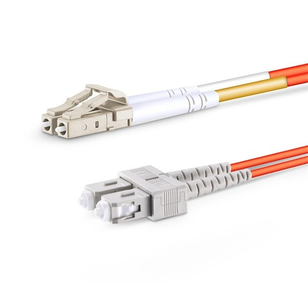
One of the most frequent problems in fiber optic networks is signal loss —the gradual reduction of optical power as light travels through the cable. Causes include excessive bending, dirty connectors, or poor splicing. Check for sharp bends or kinks along the cable route. Fiber-optic cables are the backbone of modern connectivity—powering 5G networks, global internet backbones, and data center interconnections with near-light-speed data transmission. While these cables are engineered for durability (with some rated to last 25+ years), they are not invulnerable. Even. When fiber optic cable is stretched or compressed, it can cause physical damage. This is a situation where a cable maintenance is required. This can cause either microbends or macrobends. However, in real-world installations, whether underground, aerial, or in harsh industrial environments, fiber cables can and do fail. Understanding the common causes of. Fiber break, broken fiber is divided into two types: partial interruption and the entire optical cable interruption Partial interrupts are of the following categories: The first reason is that the fiber core is interrupted due to external force extrusion or excessive bending. This guide lists the actual, field-proven problems technicians encounter most often and gives step-by-step troubleshooting actions you can copy into your maintenance routine. Keep. Understanding the common causes and solutions helps maintain stable and efficient connections.
[PDF]
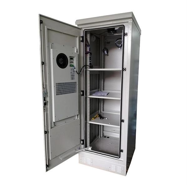
Papua New Guinea's rugged terrain and growing energy demands make outdoor energy storage cabinets a critical component for reliable power distribution. This article explores the unique requirements, technological advancements, and trusted manufacturers serving this dynamic market. This article explores how customized lithium battery systems address remote electrification, mining operations, and renewable integration while boosting sustainability. However, high temperatures and humidity pose challenges for battery longevity. This is where liquid cooling plate technology becomes. Summary: Papua New Guinea's growing energy demands require tailored battery storage systems to support renewable integration, rural electrification, and industrial growth. This article explores how customized energy storage solutions address local challenges, backed by case studies and industry. The project encompasses the construction of a solar and battery energy storage system (BESS) minigrid to be built on the island of Buka, within the Bougainville region. It will address the electricity needs of the region, which relies heavily on diesel generators. The deadline for applications is. Designed for remote locations, it integrates solar controllers, inverters, and lithium battery packs to ensure stable and continuous power for telecom equipment, surveillance systems, and off. Design engineers or buyers might want to check out various Lithium Battery Storage Cabinet factory &.
[PDF]

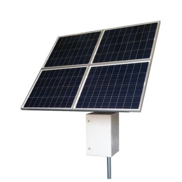
Solar energy offers data centers a path to reduce their carbon footprint and operational expenses. Major tech companies like Google and Apple are already leading the way, demonstrating that solar-powered data centers are environmentally responsible and economically viable. Data centers are the backbone of our digital world, powering everything from streaming services and cloud storage to remote work platforms and IoT devices. As our reliance on digital infrastructure grows, so does the energy consumption of these mission-critical facilities. Currently, data centers. Solar offers clean power at predictable costs, can be built fast at many scales, and pairs well with batteries to deliver reliability. In this article, we explain why data centers use so much energy, how solar powers data centers, how batteries and microgrids keep servers online, and why these. 2022 to 35 gigawatts (GW) in 2030. The United States accounts f d tap into suitable energy sources. Renewable energy is the answer, but it must be cost-efective, able to meet enormous demand without inte zed by explosive growth and demand. The emergence of AI, data streaming, cloud computing, and.
[PDF]

In this tutorial video, we will show you step-by-step how to safely and effectively remove an optocoupler from a circuit board using desoldering wick. We will walk you through the tools you will need, the proper technique for using the desoldering wick, and the precautions to take to av. more In. Whether you're replacing a faulty component, salvaging parts from an old board, or correcting a soldering mistake, knowing how to desolder effectively is essential. This guide will walk you through the tools, techniques, and best practices for desoldering components from a circuit board safely and. Desoldering is a process that removes the solder and components from a printed circuit board or any other type of electronic assembly. This is a meticulous process and it can easily damage the board, or the components, if not properly done. Thus, it is important to know how to desolder properly. If you're desoldering a battery from a circuit board, use flush cutters to cut each wire one-at-a-time to isolate the battery before you desolder the wires. Whenever possible, create an indirect path by soldering connectors onto the battery and the circuit board. This reduces the chance of an. Sorry, an unexpected error has occurred. Why Publish? The Ultimate Guide to Desoldering: From using desoldering irons to sketchily knocking breadboard components off on the side of a table, there are tons of ways to remove components from a circuit board.
[PDF]
Our Circuit Detail Labels are designed to provide clear identification of electrical circuits on distribution boards, fuse boxes, and consumer units. Premium Quality Non-Tearable Vinyl Paper Circuit Breaker Directory Label with Fuse Stickers for Fuse Panel, Marker Sign for Electrical Panel. House or Commercial Use 170 Circuit Breaker Decals - 100 AMP Set - Vinyl Labels for Breaker Panel Boxes - for Home or. To verify or get additional information, please contact The Home Depot customer service. Eaton's Universal Panel Circuit Directory Kit consists of two 42-circuit directory cards and two plastic sleeves. The directory is quick and easy to install in your load center using the adhesive backing on the. Panelboard Number Tabs (1-42). For any Panelboard up to 42 Circuits. The trademarks Walmart and the Walmart Spark design are registered with the US Patent and Trademark Office. VA law requires us to inform you about your data rights. Writable and personalised options available in multiple sizes and designs. Personalised Circuit ID Labels. Choice of Colours Circuit. Generate a customized Breaker Box Label Excel Template Generator Excel template using Sourcetable AI. Tell Sourcetable what type of spreadsheet it should make and it will generate it for you from scratch. Work smarter with AI. Organizing your electrical panel requires a clear, well-designed breaker.
[PDF]
In, a transimpedance amplifier (TIA) is a to converter, almost exclusively implemented with one or more (opamps). The TIA can be used to amplify the current output of, photo multiplier tubes,, and other (that are modeled well as a ) into a usable voltage.
[PDF]
Here we design a LASER diode driver circuit with adjustable voltage regulator LM317 to drive red color 650nm 50mW laser diode. The function of the Laser diode driver is to provide a constant current to t.
[PDF]
This guide breaks down everything you need to know about electrical distribution boxes in plain English. We'll explain what they are, the different panel types you'll encounter, NEC 408 requirements that govern their installation, and common applications for each type. The power distribution boxes deliver electricity from the main electrical main to other circuits. Several distribution boxes are designed for specific use in offices or industries. Main Distribution Board (MDB) 2. Each. Distribution boxes, also known as electrical distribution boards or panels, are pivotal components in electrical systems, ensuring the safe and organized distribution of electrical power throughout residential, commercial, and industrial environments. It receives power from the main electrical supply and divides it into separate circuits, each. Electrical control panels and distribution boxes are the backbone of modern electrical systems. From powering homes and industrial facilities to supporting medium-voltage infrastructure, these enclosures ensure safe, efficient, and reliable power distribution. Whether it's a small electrical.
[PDF]