
In this tutorial video, we will show you step-by-step how to safely and effectively remove an optocoupler from a circuit board using desoldering wick. We will walk you through the tools you will need, the proper technique for using the desoldering wick, and the precautions to take to av. more In. Whether you're replacing a faulty component, salvaging parts from an old board, or correcting a soldering mistake, knowing how to desolder effectively is essential. This guide will walk you through the tools, techniques, and best practices for desoldering components from a circuit board safely and. Desoldering is a process that removes the solder and components from a printed circuit board or any other type of electronic assembly. This is a meticulous process and it can easily damage the board, or the components, if not properly done. Thus, it is important to know how to desolder properly. If you're desoldering a battery from a circuit board, use flush cutters to cut each wire one-at-a-time to isolate the battery before you desolder the wires. Whenever possible, create an indirect path by soldering connectors onto the battery and the circuit board. This reduces the chance of an. Sorry, an unexpected error has occurred. Why Publish? The Ultimate Guide to Desoldering: From using desoldering irons to sketchily knocking breadboard components off on the side of a table, there are tons of ways to remove components from a circuit board.
[PDF]
This template provides a structured approach to evaluating distribution boards, ensuring they meet safety and compliance standards. Using this checklist, you can identify potential issues early, enhance safety, and ensure regulatory compliance. It covers clear access and housekeeping, panel integrity and corrosion, proper mounting and canopy protection, junction box condition, covered switches and displays, and. Check for signs of corrosion or rust. Inspect for any physical damage to the enclosure. Ensure that all labels and warning signs are legible. Verify that the box is securely mounted and that there are no loose connections. Internal Inspection Open. The document is an electrical installations inspection checklist designed for weekly use, encompassing various safety and compliance criteria such as the condition of distribution boards (DBs), cables, and the grounding of electrical equipment. It includes checks for general condition, insulation, busbars, connections, auxiliary equipment, and circuit. Architects and Engineers Electrical Contractors Plumbing Contractors City and County Building Inspectors Manufacturers of Electrical Equipment Pacific Gas and Electric Company Employees 2022–2023 Edition (Supersedes All Previous Editions and Revisions) The Electric and Gas Service. An electrical distribution board inspection checklist is crucial for ensuring the safety and reliability of electrical systems.
[PDF]
A junction box contains two trade size 3 raceways on the left side and one trade size 3 raceway on the right side. raceway on the right side, and one 3-in. raceways on. Pull boxes, junction boxes, and conduit bodies must be sized to allow conductors 4 AWG and larger to be installed without damage to the conductor insulation. The NEC provides sizing requirements in 314. Keep in mind these requirements address conductors used for general wiring, such as those. Article 370 covers the installation and use of all boxes (and conduit bodies) used as outlet, junction, or pull boxes, depending on their use. You're reading an older article from ELECTRICAL CONTRACTOR. Some content, such as code-related information, may be outdated. Visit our homepage to view the. When conductors enter an enclosure with a removable cover, such as a conduit body or wireway, the minimum distance from the raceway entry to the removable cover is the bending distance listed in Table 312. 6 (A) for one conductor per terminal [314. This approach helps in the safe organization of wires. To stop a fire from beginning or spreading, sparks are contained by fireproof connections and boxes. In this reading, we will delve into the definition of a. For example, a box is needed for eight 2-inch conduits. Each conduit will contain 2/0 conductors that will be spliced within the box. What is the minimum length required for the left/right (“X”) dimension? The minimum distance required because of the.
[PDF]

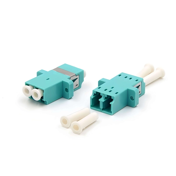
In this post, we'll walk you through practical tips, essential tools, common pitfalls, and the techniques that will help you get your fibre patch cable installations right the first time. Correct patch-cord installation is essential for maintaining low insertion loss, stable return loss, and long-term reliability in both indoor and outdoor fiber networks. Proper handling, routing, cleaning, bend-radius management, and connector alignment ensure that the optical link meets design. Proper connection of fiber optic cables is essential to harness these benefits fully, as even minor errors can lead to significant performance issues like signal loss. This guide addresses expert-certified best practices applied by professionals in the telecommunications, data. Yingda outlines the tools and materials needed to install fiber optic patch cords, as well as a complete step-by-step installation guide and important safety considerations to take. We will also tie this procedure back to the earlier discussion of multi-mode fiber types (OM1 to OM5) and connection. The Flex-Angle boot is designed to bend any angle or direction from straight to 90°. OMC flex angle boots for LC&SC fiber optic connectors are available on any single-mode or multimode patch cord. They are designed so the installer can pre-bend the boot into any direction or angle. Selecting the correct fibre patch lead is crucial for optimising signal performance and.
[PDF]

A ladder type cable tray tee is a fitting used to create a branch in a cable tray system, allowing cables to be routed in three directions. Its "T" shape provides a secure and efficient way to split cables from a main tray into two separate paths, ensuring organized and flexible. A cable tray tee and tee cover are components used in cable management systems to support and protect electrical and data cables. Here's a brief explanation of each:. Rigid steel cable tray tee fitting with zero tangent, safety bottom, and full accessory support. ventilation to heat producing cable such as power communication and other with the same or different width of the cable run. All fittings are available in sizes and types corresponding to the straight cable tray sections. These fitting are including: elbow, horizontal cross, vertical inside. NOTE : Equal or un equal tees can be supplied. When ordering state widths W1xW2xW3.. Office: 147/22 Nguyen Sy Sach Street, 15 Ward, Tân Binh Dist, HCMC,VN. Is it possible to connect 2 cabletrays with a "branch piece (left picture)" instead of a "tee (right picture)". The tee has 3 connectors, the branch piece only has 1 connector. I would like to ajust the "Type properties -> Fittings -> Tee" with the branch family, but can't get it accomplished.
[PDF]