
Appropriate Ethernet cables must be used to connect with the PoE and normal switch by means of a physical connection. Use the cables correctly and plug each end cable to the corresponding port on each switch to provide stable networking. So, the PoE switch is a networking device through which the PoE passes. In addition, this switch has numerous Ethernet ports that link to network segments, which also help with power and data. Can I use a PoE switch as a regular switch? (Answered) A POE switch gives power to devices that support the protocol, like cameras and access points. A regular switch, on the other hand, merely supplies the internet signal. A regular. A PoE switch simplifies network installation by providing power and data transmission over a single Ethernet cable. However, to take full advantage of a PoE switch, it's crucial to understand how to use it properly. This eliminates the need for separate power adapters, reducing cable clutter and. Just reuse teh POW cables that are alredy up there, and instead of them connecting to POE Wifi adapters, connect them to a POE switch (which would also allow me to add more cameras later) and drop a line from that switch into the main switch in the house. In this article we will uncover the subject matter of PoE switches and watch how they are necessary for the network design.
[PDF]
PoE switches (Type 1) comply with the IEEE 802. 3af standard, which specifies the maximum power delivered over Ethernet cables. 4 watts of power per port, while PDs can consume up to 12. UPoE supports higher-powered devices, including advanced Wi-Fi 6 APs, video conferencing endpoints, large-screen digital signage, and compact desktop switches. The latest IEEE standard (802. 3bt), supporting up to 90 W per port. UPoE+ can power advanced devices like LED lighting systems. Power over Ethernet (PoE) is a widely used LAN technology that provides DC power to endpoints over existing copper Ethernet cabling used for data connectivity. This eliminates the need for separate power supplies for devices such as IP cameras, VoIP phones, or wireless access points.
[PDF]

Enable or disable the PoE function on S series switches: 1. system-view. Huawei's comprehensive portfolio of products and solutions enables you to realize smooth digital transformation and rapid growth of virtualization, Big Data, and cloud services. Huawei switches already help customers achieve success in industries such as finance, Internet, retail, education. Welcome to our user-contributed teardowns on the hottest new gadgets. You can write your own teardown, check out how others are contributing with their teardowns, and even check out disassembly photos and comprehensive hardware analysis. Why should I create a teardown? The Lenovo M910s has been. One of them in particular involves the use of Power-over-Ethernet (PoE), but as I don't already have any “standards-complaint” PoE equipment, I needed a cost-effective means of getting a workable set-up. In the early days of 100BASE-TX Ethernet, only two of four pairs of the Ethernet cable were. If one or multiple PoE chips of a PSE are suspended, the port connected to a PD cannot detect the suspension and fails to power the PD. In this case, you can reset the PoE chip. The PoE chip is reset. If PoE power modules are working normally, check whether the PoE card and DIMM are working normally. If the register. Only electrical interfaces of switch models with PWR or PWH in the device names support the PoE function. All views Before using the PoE function, run the display poe device command to check.
[PDF]
Our Circuit Detail Labels are designed to provide clear identification of electrical circuits on distribution boards, fuse boxes, and consumer units. Premium Quality Non-Tearable Vinyl Paper Circuit Breaker Directory Label with Fuse Stickers for Fuse Panel, Marker Sign for Electrical Panel. House or Commercial Use 170 Circuit Breaker Decals - 100 AMP Set - Vinyl Labels for Breaker Panel Boxes - for Home or. To verify or get additional information, please contact The Home Depot customer service. Eaton's Universal Panel Circuit Directory Kit consists of two 42-circuit directory cards and two plastic sleeves. The directory is quick and easy to install in your load center using the adhesive backing on the. Panelboard Number Tabs (1-42). For any Panelboard up to 42 Circuits. The trademarks Walmart and the Walmart Spark design are registered with the US Patent and Trademark Office. VA law requires us to inform you about your data rights. Writable and personalised options available in multiple sizes and designs. Personalised Circuit ID Labels. Choice of Colours Circuit. Generate a customized Breaker Box Label Excel Template Generator Excel template using Sourcetable AI. Tell Sourcetable what type of spreadsheet it should make and it will generate it for you from scratch. Work smarter with AI. Organizing your electrical panel requires a clear, well-designed breaker.
[PDF]
Each version of Nintendo Switch has its own dedicated SD card slot. Adding a microSD card to your Switch is pretty easy. You will find the Nintendo Switch memory card slot at the back side of the Switch near the bottom of the console. Struggling to find the microSD card slot on your Nintendo Switch? This quick guide will show you exactly where to locate it and how to properly insert or remove your memory card to expand your console's storage. 512 microSDXC Memory Card, UHS-I, C10, U3, V30, A2, Full-HD Video, Up to 100 MB/s, Expanded Storage for Nintendo-Switch, Gaming. This guide will tell you everything you need to know about the Nintendo Switch 2's internal storage and memory, how many games you can store, and how you can increase your storage space. On this page: Nintendo Switch 2: Internal Storage - How Many Games Can You Store? 1. This will not change whether downloadable software or software from a game card is being played. Game save data cannot be saved or copied to a microSD Express card. Nintendo Switch Online members can use Save Data Cloud. These cards are small, but they can significantly expand the console's storage capacity, allowing you to download and store more games and content. The memory card slot is cleverly hidden to maintain the sleek design of the console, which can make it a bit tricky to find if you are not familiar. Check each product page for other buying options.
[PDF]
This manual describes Inspect, a command-line tool for debugging TNS C/C++, COBOL, FORTRAN, Pascal, Screen COBOL, and TAL programs and snapshots on HP NonStopTM TNS/R and TNS/E systems. MFT (Mellanox/NVIDIA Firmware Tools) is a set of firmware management utilities for querying firmware details, performing firmware upgrades, and other configuration tasks. It includes four main components: mst, mlxburn, flint, and Debug Utilities. For full specifications, refer to the official. All commands were tested on HP/Aruba 5400 switches (specifically 5406Rzl2), but will work on any model with recent firmware versions (16. x or newer), except for the hardware features unavailable on smaller models, like VSF. This publication supports J06. 03 and all subsequent J-series RVUs, H06. Show general info: current CPU load, uptime, memory used/free, software. The HP 1-Port 1GbE Flex IO NIC is designed to work in the Flex IO port of select HP systems. Refer to platform specifications for compatibility. It utilizes a Realtek RTL8153 10/100/1000 Ethernet controller to provide an additional 1GbE LAN Port. 3az-2010, also known as Energy. HPE Insight Diagnostics is a hardware diagnostic tool. To start iLO with keyboard and monitor connected to the box - press F8 while booting Invoke virtual serial port. Starting text console. Press 'ESC (' to return to the CLI Session.
[PDF]

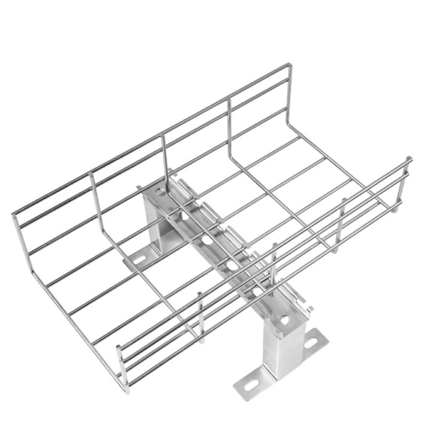
A ladder type cable tray tee is a fitting used to create a branch in a cable tray system, allowing cables to be routed in three directions. Its "T" shape provides a secure and efficient way to split cables from a main tray into two separate paths, ensuring organized and flexible. A cable tray tee and tee cover are components used in cable management systems to support and protect electrical and data cables. Here's a brief explanation of each:. Rigid steel cable tray tee fitting with zero tangent, safety bottom, and full accessory support. ventilation to heat producing cable such as power communication and other with the same or different width of the cable run. All fittings are available in sizes and types corresponding to the straight cable tray sections. These fitting are including: elbow, horizontal cross, vertical inside. NOTE : Equal or un equal tees can be supplied. When ordering state widths W1xW2xW3.. Office: 147/22 Nguyen Sy Sach Street, 15 Ward, Tân Binh Dist, HCMC,VN. Is it possible to connect 2 cabletrays with a "branch piece (left picture)" instead of a "tee (right picture)". The tee has 3 connectors, the branch piece only has 1 connector. I would like to ajust the "Type properties -> Fittings -> Tee" with the branch family, but can't get it accomplished.
[PDF]

Cable Trays* — Max two 24 in. (610 mm) wide by max 6 in. (151 mm) deep open-ladder cable tray with channel-shaped side rails formed of 0. 54 mm) thick aluminum or min 0. In practice, cable tray dimensions are a system of interrelated measurements —width, depth, length, and material thickness—that directly affect cable fill compliance, heat dissipation, structural loading, and long-term expandability. From an engineering standpoint, cable tray dimensions are not. Perforated Cable Tray System expertly constructed from high-grade stainless steel, offering exceptional durability and resistance to corrosion. With side height 100mm. A properly designed and installed cable tray system will provide. Studs — Wall framing to consist of wood studs or channel shaped steel studs. Wood studs to consist of nom 2 by 4 in. Additional studs shall be used to completely frame. Best Size: Here, deep trays (75mm to 150mm) are used since power cables are typically thick and heavy. Data cables, such as your Wi-Fi or computer ones, are extremely sensitive. They do not get hot; however, they do not like to hang or sag. In case a data cable folds in an excessive manner, the. ect the minimum bend ra-dius for cables as they exit the bottom of the cable tray. A rung spacing of 6 to 9 inches (150 to 230 mm) is preferable when the cable tray cont d for instrumentation and control applications that require additional protec eferred to support and protect numerous small.
[PDF]

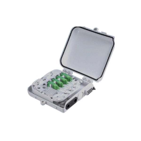
An Optical Splitter, also known as a beam splitter, is a passive optical device that divides a single input optical signal into two or more output signals. Conversely, it can also combine multiple signals into one. Knowing the difference between a splitter and an optical coupler helps you build better networks. You make your network work better when you pick the right device for each job. You can connect many users to one port with 1:n or 2:n splitters. By dividing a single optical signal from a central Optical Line Terminal (OLT) into multiple outputs for Optical Network Terminals (ONTs) at users' homes, splitters eliminate the need for dedicated fibers to each residence—slashing infrastructure costs while scaling network reach. This guide. In a Passive Optical Network (PON), a single optical fiber carries massive amounts of data using light. Signal Input: The fiber splitter receives the optical signal from the upstream network node and enters the splitter through the input fiber. Signal Distribution: Inside the splitter, according to the design structure and different. Splitters are passive optical devices that divide or combine optical signals, and they come in various types, including power splitters, uneven splitters, and wavelength-division multiplexing (WDM) splitters. Each type serves specific applications, enabling efficient use of optical infrastructure.
[PDF]

This diagram shows how the RJ45 cable is connected to the PoE switch, allowing it to power devices such as IP phones and cameras. In this article, we will explore the wiring diagram for a PoE switch, which provides a visual representation of how the switch connects to various devices. Each device is represented by a. Do you want to set up a new computer network in your home or office? Chances are, you'll need a Poe switch wiring diagram. Not only do these diagrams provide all the information you need to install a network, but they also help make the process easier and more efficient. For those who don't know. A PoE Switch, also known as Power over Ethernet Switch, is a network device that allows users to power and connect devices such as IP cameras, VoIP phones, and wireless access points. In essence, a PoE Switch can be described as regular switch with added ability of Power over Ethernet which allows. PoE technology enables the transmission of both data and power over a single ethernet cable, simplifying network setups and eliminating the need for additional power sources. This is particularly useful in scenarios where devices like IP cameras, wireless access points, or VoIP phones need to be. Here, you can see the details, Keep the copper strips towards your face and count the pin number or pin position from left to right. The T568B also has a total of eight pins and sight different colors.
[PDF]

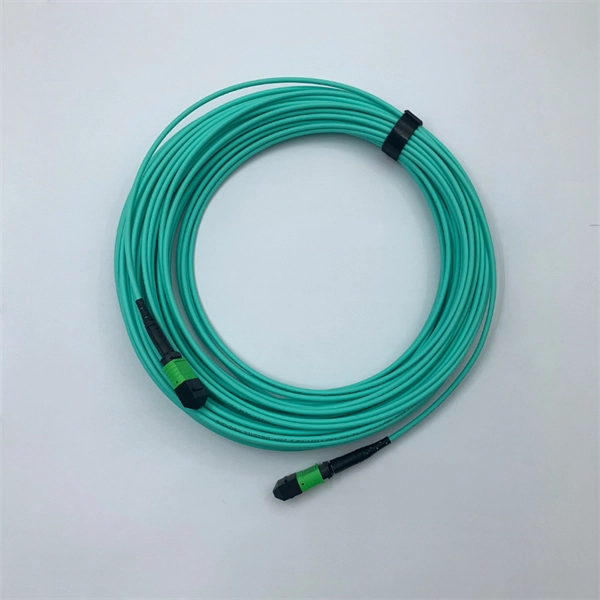
Power over Ethernet (PoE) does not work directly over fiber-optic cables because fiber-optic cables are designed to transmit data using light, and they do not conduct electricity. PoE requires copper cables (such as Cat5e, Cat6, or Cat6a) to deliver both power and data. Power over Ethernet (PoE) is a useful technology in powering remote devices, but as we see with any copper network cable, the challenge lies in the limited distances of UTP cabling. The maximum distance for Power over Ethernet (or any network data transmission) is 100 meters or 328 feet. However, selecting the right PoE switch requires careful consideration of factors such as projected organizational growth and device. In the field of network cabling and device power supply, Power over Ethernet (PoE) technology has become widely adopted due to its ability to transmit both data and power over a single Ethernet cable. In industrial environments, industrial switches are key network devices that are adapted to harsh. IP cameras that are part of a modern surveillance system are deployed using PoE technology that involves the use of copper based network cabling like CAT5e or CAT6 that has a data transmission limit of 100m (328ft). While that is adequate for installations for a home or small business, large scale. They have dual-port choices and are easy to set up. Media converters work well in many places. You do not have to worry about distance.
[PDF]
