Bottom price Gpon Sfp Onu - 100GBASE-LR4 QSFP28 1310nm 10km Hi-Optel HQSFP28-2L2 module – Hi-optel Detail: A block diagram of QSFP28 LR4 optical transceiver is shown below ● 100GBASE-LR4 100G Ethernet ● QSFP28 MSA. Digital diagnostics monitoring function is available. No procurement opportunity was found matching these criteria. UNDP-RFP-2026-083; Baseline Assessment of Agricultural Productivity in Dadu. Superxon 50G ONU transceivers are compliant to the latest releases of the QSFP28 MSA. 3V, and. An Optical Network Unit (ONU) is a critical device in Passive Optical Network (PON) systems that serves as the endpoint at the customer's premises. It converts optical signals transmitted via fiber into electrical signals for use in homes, offices, and data centers. ONUs support a wide range of. VSOL offers a wide range of XPON/GPON/EPON ONU/ONT, integrating Wi-Fi, CATV, and VoIP for high-speed, simplified network deployment. Sticking for the basic principle of "Super Top quality, Satisfactory service",We've been striving to be an excellent business enterprise partner of you for Single Mode Fiber Module, Sfp28 Bidi, Sfp+ Mmf, Our intention is to assist clients understand their ambitions. We are earning wonderful. Discover our selection of GPON, EPON, and XG (S)PON ONT/ONU devices. Choose from reliable Optical Network Terminals for seamless connectivity and efficient network solutions.
[PDF]

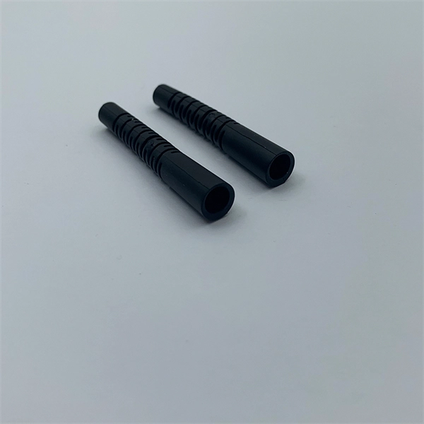
Download new and previously released drivers including support software, bios, utilities, firmware and patches for Intel products. trol I/O is desired. The Q-SYS Core 24f satisfies a broad spectrum of application needs from meeting room environments, conferencing systems, retail establishments, houses of worship, judicial environments, education institutions and other general purpose pro essing applications. A Core 24f may be. That change is why correct leads and connections matter for system stability and lifespan. Please sign in or register for an Intel account. Automatically update your drivers and software Use this tool to identify your products and get driver and. Purpose: This connector serves as the main junction, transmitting essential electrical currents from the supply unit to the motherboard. Design: It features a distinct arrangement of multiple connectors, each designated for specific functions, ensuring balanced and stable power distribution. Product replacement Get replacements and find substitutions for discontinued Schneider Electric products. Where to buy Search our network of verified distributors with over 15,000 sales outlets. Communications bus and supply power terminal blocks, functions, ratings, requirements, and cables provides information about the functions, ratings, and requirements for the communication bus and supply power terminals; and guidelines for wire sizes, cable types, and cable lengths when wiring the.
[PDF]

Cable tray support quantity can be calculated using a simple formula: Support Quantity = Total Length ÷ Support Spacing + 1 20 ÷ 2 + 1 = 11 supports In a typical project, a 20-meter cable tray with 2-meter spacing requires 11 supports. Calculating the cable tray support quantity is a crucial part of electrical installation projects. In complex engineering environments, the. Properly sizing your cable tray is critical for safety and compliance. Our free calculator helps you determine the correct tray size based on NEC and IEC standards. This calculator features an interactive interface with advanced visualizations. Open the full calculator for the best experience. Save your cable tray sizing calculator results as branded PDF. Calculate NEC-compliant wire basket cable tray fill, load capacity, and hardware requirements for professional installations. We independently provide precision steel tools, calculators, and expert resources for steel, metalworking, construction, and industrial projects. IEC 61537 covers cable tray and cable ladder systems for the support and accommodation of cables, while NEC Article 392 governs cable. What is the fill capacity and remaining capacity of my cable tray? Calculate cable tray sizing and fill capacity based on tray dimensions, cable diameter, number of cables, and maximum fill percentage per electrical code. Determine whether cables fit within safe fill limits. Cable tray fill.
[PDF]

Step-by-step instructions on how to install the Polylok 12" distribution or drainage box. In this guide, we'll break down everything you need to know to install a distribution box correctly and confidently. Choose the right box based on environment (indoor/outdoor), load capacity, and durability. Check for proper IP/NEMA ratings and material quality. Ensure safe placement: install in. The installation of a distribution box is explored in detail, highlighting advanced techniques for achieving a professional and efficient setup. This video provides valuable insights for anyon. more Distribution Box Installation: Advanced Techniques. When it comes to rigid, easy to install electrical box supports, Eaton offers a wide variety of B-Lines series electrical boxes that help reduce installation complexity. For professional installers and property owners, the mechanical components like support rods play a critical role in long-term safety and maintenance efficiency. These components ensure that heavy-duty. Whether you are an electrical contractor or a construction brigade, knowing how to properly and safely install distribution boxes is the basis of ensuring the safe operation of the entire system.
[PDF]
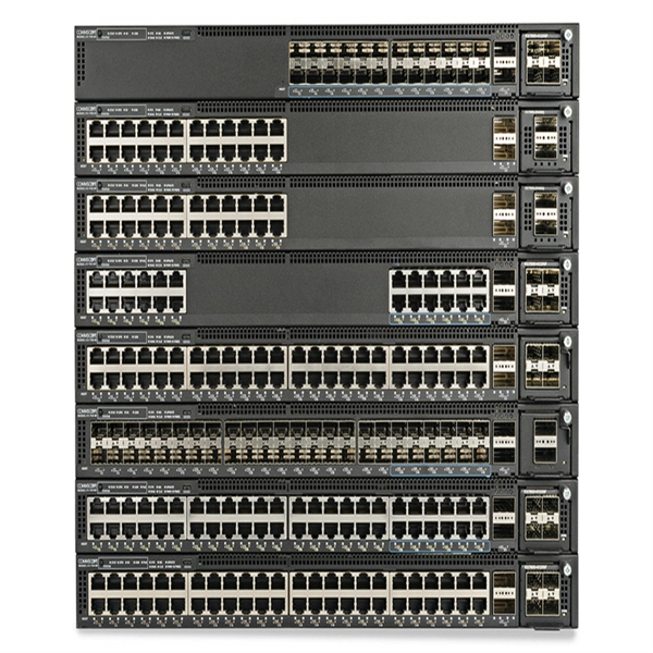
You can connect two Switch consoles via a network in two ways: Wi-Fi or Ethernet cable. For a more stable wired connection, use a Nintendo Ethernet adapter and a category 5e or higher cable. Important: A USB LAN Adapter can be connected to Nintendo Switch Lite using a licensed accessory, such as the Dual USB PlayStand for Nintendo Switch Lite from HORI. Nintendo Switch can connect online with a wireless connection or, when through use of a LAN adapter, a wired connection. Game sharing between two Switch consoles involves setting up your Nintendo. TL;DR: Is there a way to have two different (unreliable) ISPs connected to a single network switch, so that when one drops out, the home network is automatically switched to the other ISP? --- Hi all! I am a networking hobbyist, and I built out a home network for a family friend of mine living in. To view and connect your Nintendo Switch to either the 2. 4 GHz or 5 GHz Wi-Fi band, follow these steps:. 4 GHz and 5 GHz. But before we get into the details, it's essential to understand that the Nintendo Switch supports both 2. 4GHz and 5GHz WiFi frequencies, ensuring faster and more reliable connectivity. Cisco ® Catalyst ® 9200 Series switches extend the power of intent-based networking and Catalyst 9000 hardware and software innovation to a broader set of deployments. With its family pedigree, Catalyst 9200 Series switches offer simplicity without compromise – it is secure, always on, and IT.
[PDF]

Professional-grade cantilever support arm specifically designed for cable tray installations. Features a welded flat mounting plate construction for secure attachment. Manufactured by nVent CADDY, this sturdy support solution provides reliable cable management infrastructure. 0 are currently in. 15. 41x21mm horizontal support for wall fixing of cable trays, electrical conduits and other heating pipe installations, A/C, fire protection systems, etc. Excellent loading capacity. Robust and secure system. Made of steel, available in various protection systems. Available in widths from 100 to 1000. Cable Support Systems are well designed to provide necessary support for cable trays, cable ladders and trunkings. Cable supports are manufactured according to common standards from high quality raw materials. Requires only one bolt for quick fixing and is used with open face at the top. Two bolt. us-trations without notice. All illustrations, descriptions and technical information included in this document are provided as indications and can cable trays are equivalent. The mechanical and electrical characteristics, tests, certifications, overall quality management, recommendations mentioned.
[PDF]
This article will focus on the failure rates of optical modules, analyze the primary causes of failure in traditional Digital Signal Processing (DSP) modules, compare failure rates utilizing LPO technology, and discuss the advantages presented by LPO modules. Linear Pluggable Optics (LPO) are a new optical transceiver technology. The idea is simple: instead of a DSP (digital signal processor) inside the module – replacing it with transimpedance amplifier (TIA) and a driver chip with high linearity and EQ capability – LPO shifts signal processing into. Copyright 2023, Coherent. Next-generation 400G and 800G modules for data centers, AI clusters, and telecoms — validated in a European lab, ready to ship from Europe. What is Low-Power Optical Transceivers (LPO)? Linear Pluggable Optics (LPO) replace the DSP inside the optical module with linear analog components, shifting. QSFP-DD LPO TRANSCEIVER DESIGNED FOR PCIE® GEN 5. 0 over optical link, enabling scalable server disaggregation and efficient rack-to-rack interconnects ideal for AI/ML and. Led by Cisco Optics experts, this MSA quickly gained broad industry support due to its vision to create cost-effective solutions for high-density multi-terabit switching, routing, and transport networks. The goal was to define optical specifications that allow for future 100G and 400G pluggable.
[PDF]
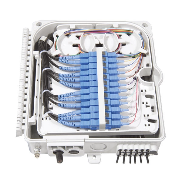
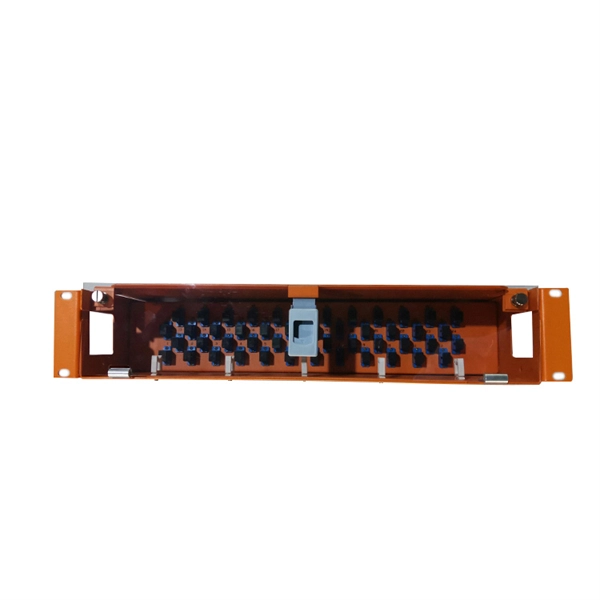
When deploying fiber optics in the field, telecommunications companies need ways to safely and efficiently store and terminate cables. As many technicians know, having the right fiber optic patch and splic.
[PDF]
Bogdan Sirbu: One example I can think of is the H2020 L3MATRIXproject. On this project, we developed a 2D matrix of 64 different transceiver and receiver cells, achieving high radix and getting an extend.
[PDF]

If a wire mesh cable tray is supporting cable with a built-in equipment grounding conductor or control or signal cables, then the tray should have a low impedance path to a non-system ground to reduce noise and remove induced or stray currents. Cable tray may be used as the Equipment Grounding Conductor (EGC) in any installation where qualified persons will service the installed cable tray system. There is no restriction as to where the cable tray system is installed. The metal in cable trays may be used as the EGC as per the limitations. Cable tray systems have become an essential component in the infrastructure of modern commercial buildings, smart offices, data centers, and various industrial facilities. These systems provide an efficient and adaptable solution for managing a wide range of cables, including power cables, control. Cable tray grounding wire is the safety connection that links your electrical system's cable tray to the ground. This provides a safe path for any stray electrical currents to flow safely into the earth, avoiding damage to your equipment and reducing the risk of electric shocks. The main purpose of. Do Cable trays have to be grounded? It sounds like a dumb question but if a cable tray has no individual wires in it only raceways, it is not likely to get energized. It involves connecting cable trays to the facility's grounding system, providing a low-impedance path for fault currents and protecting personnel.
[PDF]
5″ hard drive with a storage capacity of 80GB and featuring a IDE interface. ST380011A Seagate Barracuda 80GB 7200RPM ATA/EIDE 2MB Cache 3. 5-inch Low Profile (1. All information about the Seagate ST380011A hard disk drive: technical parameters, failure. 8-Mbyte buffer on: ST3200822A, ST3160023A, ST3120026A, and ST380013A High instantaneous (burst) data transfer rates (up to 100 Mbytes per second) using Ultra DMA mode 5. Giant magnetoresistive (GMR) recording heads and EPRML technology, which provide the drives with increased areal density. Manuals and User Guides for Seagate Barracuda 7200. 7 ST380011A Drive manuals available for free PDF download: Product Manual, Installation Manual Figure 3. Breather Filter Hole Location Figure 4. Ultra ATA. 1. 7 Plus • ST3160023A • ST3120026A • ST380013A Barracuda 7200. 7 • ST3160021A • ST3120022A • ST380011A • ST360014A • ST340014A These. HITACHI HDS721032DLE630 (320 GB S-ATA Gen3) SAMSUNG HS10XJC (100 GB IDE) SEAGATE ST9250612NS (250 GB S-ATA Gen3) Device manufacturers may change any parameters without prior notice. There is no warranty that the information listed here is complete and accurate. If you encounter any improper value. Our goal is to provide you with a quick access to the content of the user manual for Seagate Barracuda ST380011A. If looking through the.
[PDF]
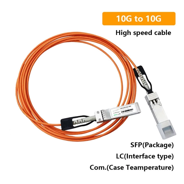
Most SFP fiber optic modules use LC connectors, while SC connectors are mainly found in legacy networks and MPO/MTP connectors are used for high-density cabling rather than directly on standard SFP modules. While the small size of fibre optic connectors does not mean they play a minor role, the type of connector you use affects the overall efficiency of light transmission across the fibre network. Of the more than a dozen types of fibre-optic connectors available, the four most commonly used today are. Fiber optic connectors are the unsung heroes of modern networking. They are small, often overlooked components, yet they are essential for ensuring high-speed, low-loss, and reliable optical transmission. This connector landscape reflects how modern SFP deployments prioritize port density and. A fiber optic connector is a mechanical device used to align and join optical fibers, enabling light to pass through with minimal loss. Unlike fiber splicing, which is permanent, connectors allow for easy connection and disconnection of cables, making them ideal for maintenance and flexibility in. Fiber connector types LC, SC, FC, ST, MTP, and MPO are widely used in past and present. What are the differences between them? Who is the most popular one? Find the answer in the article. As a leading provider of fiber optic solutions, Weunion understands the critical role of connectors in modern networks.
[PDF]
Learn about the two main types of fiber optic couplers: fused and planar. Fused couplers are cheap and work well. Pick the port setup that fits your needs. When it comes to proper fiber optic coupler selection, you will have to consider the effectiveness of the application in splitting and distributing optical signals without losing or interrupting the signal. If you choose poorly, the server signal will not be strong, there will be delays in. Fiber optic adapters, also known as couplers, play a crucial role in fiber optic networks by providing a connection point between two fiber optic connectors. They enable seamless and reliable optical signal transmission between different fiber optic cables, connectors, or devices. In this tutorial. This comprehensive guide explains what fiber optic adapters are, their common types, key selection criteria, cleaning best practices, frequently asked questions, and how customized connector solutions can benefit B2B projects in telecommunications, data centers, and industrial networks. What Is a. This small device connects or joins optical fibers together. It helps networks grow and change when needed. It provides an objective comparison to help you identify the best solutions for your networking needs. Unlike fiber splicing, which is permanent, connectors allow for easy connection and disconnection of cables, making them ideal for maintenance and flexibility in.
[PDF]

This video shows real on-site footage of electrical installation, demonstrating safe and standardized wiring methods used by professionals. more Learn how to wire a distribution box step by step! This video shows real on-site footage of. Material preparation: Prepare the required circuit breakers, wires, wiring ties and other materials, and ensure that they meet the design drawings and installation requirements. Location determination: Determine the installation position of the circuit breaker according to the position of the. Learn how to install a distribution box safely and correctly. Covers wiring, placement, standards, and expert tips for a compliant setup. A distribution box is the heart of any electrical system. It takes the incoming power and safely distributes it to different circuits throughout your building. And all the switching and protective devices are installed in the distribution box. Single Phase Distribution Box generally consists of Double Pole MCBs, Single Pole MCBs, and RCCBs. So here's what you need to know about wiring distribution panels, to make sure yours operates exactly as needed and as expected. Each circuit supplies a specific load, whether it's going to. Explosion-proof distribution boxes, vital terminal distribution equipment in power systems, play a crucial role in controlling and protecting industrial electricity in hazardous environments.
[PDF]

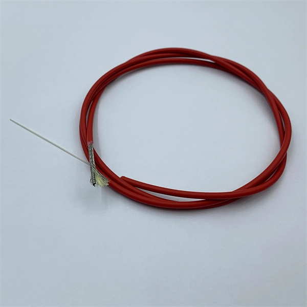
Use the SWD or JTAG interface to connect the ST-Link v2 to the STM32 microcontroller. Download and install STM32CubeIDE or another compatible IDE. Install the ST-Link USB driver (available on the STMicroelectronics. The ST-LINK/V2 is an in-circuit debugger/programmer for the STM8 and STM32 microcontrollers. The single wire interface module (SWIM) and the JTAG/serial wire debugging (SWD) interfaces facilitate communication with any STM8 or STM32 microcontroller operating on an application board. ATOLLIC, IAR and KEIL Integrated Development Environments for. How do you use SWD (Serial Wire Debug) for debugging STM32? - HackMD Using SWD (Serial Wire Debug) for debugging STM32 microcontrollers is a powerful way to monitor and control code execution, inspect registers, and analyze faults. Here's a step-by-step guide to set up and use SWD effectively: 1. In addition. This small guide will explain how to connect your debugger to your development board. There are two commonly used connectors which expose only the SWD (Serial Wire Debug) interface or the full JTAG interface. If you are using one of ST's official Nucleo or Discovery boards, you do not have to. To upload a program to a chip from Thomson Semiconductor you need an ST-Link programmer device to connect your PC. Thompson sells branded programmers, adaptors and cables. We'll use an inexpensive ST-LinkV2. They look like AVR programmers but you need to read the pinouts on the side.
[PDF]

