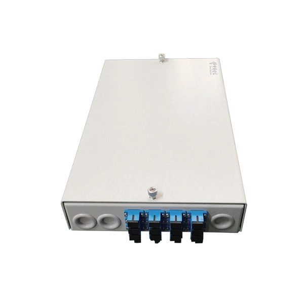
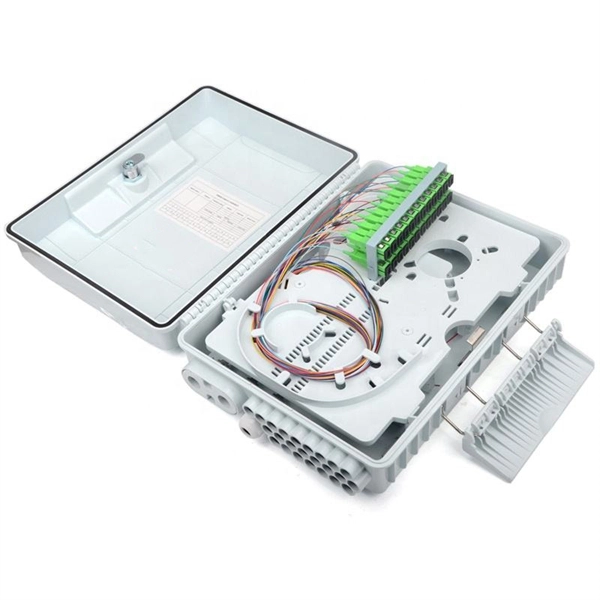
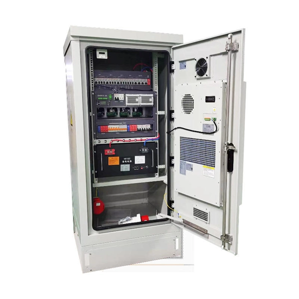
Manufacturers design fiber optic cabinets to protect fiber optic cables in indoor and outdoor environments. Also known as fiber optic enclosures or fiber entrance cabinets, these enclosures act as hubs where ca.
[PDF]

It includes first determining the type of communication system (s) which will be carried over the network, the geographic layout (premises, campus, outside plant (OSP, etc. ), the transmission equipment required and the fiber network over which it will operate. Fiber optic network design refers to the specialized processes leading to a successful installation and operation of a fiber optic network. It also involves selecting transmission equipment. It includes detailed mapping of backbone, distribution, and drop connections for FTTH, FTTP, FTTx, and enterprise networks. Building a fiber optic network is a highly technical yet vital process that enables communities and businesses to access high-speed, reliable fiber optic internet. From the initial site survey to the final fiber to the home (FTTH) connection, every stage requires careful planning, coordination, and. Designing a fiber optic network is like planning a city's road system, it needs to be efficient, reliable, and built to handle both current and future traffic. Whether you're new.
[PDF]
In September 2012, NTT Japan demonstrated a single fiber cable that was able to transfer 1 per second (10 bits/s) over a distance of 50 kilometers. Although larger cables are available, the highest strand-count single-mode fiber cable commonly manufactured is the 864-count, consisting of 36 ribbons each containing 24 strands of fiber. These high fiber count cables are used in, and as distribution cables in and networks.
[PDF]
The data from September 2023 shows that 21 countries have achieved penetration rates higher than 50%. The UAE leads the ranking with 99,3%, while Singapore positions itself second at 97,1%. Hong Kong (95,3%), China (92,9%), and South Korea (91,5%) complete the top 5 positions. This report provides an analysis of Omdia's Fiber Development Index (FDI). The FDI quantifies and ranks the level of investment in fiber optical networks across nine metrics on a country-level basis. This analysis helps industry stakeholders, including policymakers, regulators, service providers. The Mobile Connectivity Index measures the performance of 173 countries against the key enablers of mobile internet adoption. In the European. Global Fiber-optic Cable key players include ZTT, YOFC, Prysmian, HTGD and FiberHome. Global top five manufacturers hold a share about 40%. Asia-Pacific is the largest market, with a share over 60%, followed by North America, with a share about 16 percent. 8 billion by 2029 from USD 3. 4% from 2024 to 2029. Rapid expansion of data centers, cloud services, and 5G infrastructure is driving strong adoption of fiber optic solutions. 80% during the forecast period (2023-2032). This expansion is driven by surging demand for high-bandwidth networks, 5G.
[PDF]

Optical return loss is the amount of light that is reflected back to the source, this reflected light is measured at each connector and splice at each point over the entire fiber link. This is always measured in dB (decibels) and will be displayed as a negative number. The closer the number is to. The polish of a singlemode fiber endface plays a significant role in reflectance. Understand what you need before you specify. The Institute of Electrical and Building the ORL story Electronics Engineers (IEEE) recently Within a fiber-optic channel or path-released new specifications within way. Optical Return Loss (ORL) in fiber optics refers to the amount of light that is reflected back toward the source in a fiber link. ORL is usually expressed in decibels (dB) as a positive value, with. Return loss (RL) is also called reflection loss. When high-speed signals enter or exit a part of an optical fiber, such as an optical fiber connector, discontinuity and impedance mismatch may cause reflection, which is the return loss of an optical fiber. Poor ORL is commonly caused by dirty connectors, poor splices, mismatched connector types, or damaged fibers. ORL is measured using ORL meters. Home Coherent Optics Optical Return Loss (ORL) Explained Comprehensive Guide to Understanding and Managing Back-Reflections in Fiber Optic Systems What is Optical Return Loss (ORL)? Optical Return Loss (ORL) is a critical parameter in fiber optic systems that quantifies the amount of light.
[PDF]
In this comprehensive guide, we'll walk through the best practices for installing various types of fiber optic cable, from patch cords to distribution fiber, and provide practical tips to ensure a successful installation. The processes. Fiber optic installation delivers unmatched network performance for modern businesses, providing greater bandwidth capacity and superior resistance to electromagnetic interference compared to traditional copper cables. Professional installation ensures optimal performance and higher reliability for. In the spirit of self-reliance and technical mastery, we've crafted this detailed guide to empower you to take control of your own network by installing fiber optic cables yourself. In this guide, we will walk you through a step-by-step process for the installation of fiber optic cables. The number one cause of signal loss in optical fiber installations is dirt on. In this comprehensive guide, we'll cover everything you need to know about fiber optic cabling—from key components and installation procedures to best practices for network design and maintenance. What is Fiber Optic Cabling? Fiber optic cables transmit data as pulses of light through strands of.
[PDF]
This lab offers an immersive, web-based simulator that enables you to explore and experiment with key concepts in optical communication, such as signal transmission, fiber optics, modulation, and detection techniques. Opticomlib is an open source Python package for optical communications research. It is oriented to engineers who want to simulate optical communication systems using Python. The package provide binary_sequence, electrical_signal, optical_signal, and eye objects with methods for signal processing. Welcome to the Optical Communication Lab, a vital part of the B. MATLAB facilitates simulations of electromagnetic pulse propagation, saving time and resources for engineers. The study employs an ultrashort pulse with a halfwidth of 0. 65 picoseconds over a 3. PulseEvolution simulates the propagation of pulses in optical fibers by solving the NLSE using the Split Step Fourier Method. A GUI allows you to easily configure the. This study presents a novel method for simulating fiber pulse propagation using the DeepONet architecture, significantly reducing computation time compared to traditional methods. The approach is highly applicable in fields requiring real-time fiber optic system control and optimization, such as. Optical Fiber Simulation in MATLAB thesis ideas along with simulation guidance are supported by us in a very novel way for scholars if you are looking for customized services you can approach us by sharing all your project details to us.
[PDF]

Prime Minister Bridgadier (Ret'd) Mark Phillips commissioned a new multi-billion-dollar direct submarine fibre-optic cable, marking a historic moment for the region and closing the long-standing digital gap between the coastland and the hinterland. “Recognizing our responsibilities as industrialists, we will devote ourselves to the progress and development of society and the well-being of people through our business activities, thereby enhancing the quality of life throughout the world. The milestone ushers in gigabit-speed. Guyana telco ENet says it has completed a multibillion-dollar subsea cable connecting the town of Bartica – billed as the gateway to Guyana's interior – to its fibre-optic backbone. Speaking at the commissioning. These Terms and Conditions ('the Terms') govern your use of the website on the Internet located at www. com ('the Site') and are legally binding on you. The Site is owned and operated by Developing Telecoms Limited ('the Owner', 'we', 'us', 'our'). Please read the Terms before.
[PDF]
Power consumption of fiber optic cables can range from 0. 01-100 W/Gbps depending on the length of the cable (chart below). To ensure that fiber-optic connections have sufficient power for correct operation, calculate the link's power budget when planning fiber-optic cable layout and distances. The power budget is. Attenuation is the difference between the launch power of the signal from the transmitter and the power of the signal at the receiver. Each. The power consumption of coherent fiber-optical communication systems is beco-ming increasingly important, for both environmental and economical reasons. The data traffic on the Internet is increasing at a faster pace than that at which optical network equipment is becoming more energy efficient. With the growing global deployment of Fiber-to-the-Home (FTTH) networks driven by the demand for ensuring high-capacity broadband services, mobile network operators (MNOs) face challenges of excessive energy consumption (EC) of wired optical access networks (OANs). You use power budget calculations to verify whether an optical link—FTTH, ODN, backbone, or data center—can operate reliably under all. Reduced power consumption: 800G optical devices can achieve energy savings at the optical and system level, such as using more efficient modulation formats, optimizing circuit design, and reducing power density.
[PDF]

The deal, sealed in Conakry on June 12, aims to enhance digital interconnection between the two neighboring West African nations. The agreement enables reciprocal access to each country's national fiber networks through the Pamelap border exchange point. The Guinean Backbone Management Company (SOGEB) and Sierra Leone's Leoncom have signed a cross-marketing agreement to jointly leverage their international fiber optic capacities. On Thursday, 12 June, Guinea's Backbone Management Company (SOGEB) and Sierra Leone's national fiber optic operator, Leoncom, concluded a deal in Conakry to. Guinea Conakry, with its geographical challenges and rapid growth, aims to become a regional hub for connectivity in West Africa. To achieve this, the country has launched the tailor-made deployment of optical fiber networks. This project illustrates how Sofrecom's expertise contributes to this. This visualization shows the growth of the undersea cable network, global internet peering capacity, and the distribution of IP addresses via BGP announcements over time. For more details and insights, please read this. TeleGeography's free interactive Internet Exchange Map depicts over 300 active Internet exchanges and more than 500 buildings in which those exchanges reside.
[PDF]
Return-to-zero (RZ or RTZ) describes a line code used in telecommunicationssignals in which the signal drops (returns) to zero between pulses. This takes place even if a number of consecutive 0s or 1s occur in the signal. The signal is self-clocking. In digital communication systems, line encoding schemes are crucial for representing binary data efficiently and reliably. RZ (Return-to-Zero), NRZ (Non-Return-to-Zero), CRZ (Chirped Return-to-Zero), and CSRZ (Carrier-Suppressed Return-to-Zero) are distinct line coding methods, each with its own. Abstract—Analytical formulas for the power spectra of return-to-zero (RZ) optical signals generated by Mach–Zehnder (MZ) modulators are derived. This means that a separate clock does not need. The experiment aim of this experiment is to analyze the operation of Non-Return to Zero(NRZ), Return to Zero(RZ) and Pulse ration encoders and decoders. The setup created in OptSim is shown below: Each link.
[PDF]
This map shows where fiber internet service is available across the United States from all providers. Use the map controls to color by number of fiber providers or by maximum fiber speed available. Fiber-optic internet is the fastest and most reliable type of internet connection available. It uses. Let us show you the fiber data that is currently available! As one of the leading fiber location databases, FiberLocator conveniently provides you with detailed maps and information on hundreds of carriers, thousands of data centers and hundreds of thousands of on-net buildings to quickly grow and. Ask about ICT infrastructure, broadband data, or interact with the map. Show me range to terrestrial fiber nodes on the map? Is the ITU building in Geneva Switzerland within 10 km of a fibre node? Start measuring on the map to see calculations here. Analyze network nodes within a 10 km radius using. The most recent North American Fiber Deployment Report by RVA LLC Market Research & Consulting (RVA) released in January 2025 presented more records for the progress of fiber across America. A new annual record of 10. homes were passed in 2024. The FCC reviews the data and then publishes.
[PDF]
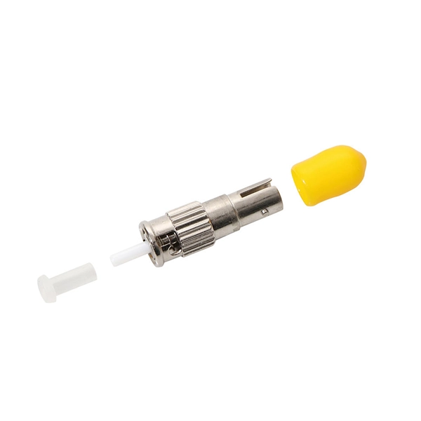
Remove the connector by carefully pulling it straight out of the port when the latch has been released. This guide outlines proper methods to safely remove fiber optic cable from modems in your home or office. As an experienced technology writer who has covered broadband advancements for over a decade, I aim to provide readers with trustworthy instructions endorsed by industry experts. Having. Fiber optic connectors are essential components in fiber optic networks, providing a reliable connection between cables and equipment. Removing these connectors requires care to avoid damaging the delicate fibers or the connector itself. Fiber optic cables are different from traditional copper cables, as they use light to transmit data, and the connectors are more sensitive. This is a popular video tutorial that is often requested by viewers. Release the latch: The SC connector is secured in place by a latch on the side. Step 1: Prepare the necessary tools and materials, including the fiber optic connector, cable stripper, fiber cleaver, and lint-free wipes. Ensure that everything is clean.
[PDF]
Fiber optic cables are essential components in modern data transmission infrastructure. They support high-speed, interference-resistant communication and are particularly effective in applications that require high bandwidth, low latency, and strong signal integrity. Unlike traditional copper or. Fiber-optic communication is a form of optical communication for transmitting information from one place to another by sending pulses of infrared or visible light through an optical fiber. The light is a form of carrier wave that is modulated to carry information. While the glass fibers inside are fragile, modern fiber cables are engineered to withstand crushing forces, extreme temperatures, and even rodent attacks—making them vital for. In the high-speed world of fiber optic communication, data travels at the speed of light. But what happens when that light fades? Optical Signal Attenuation is the single greatest factor limiting the distance and performance of your network. Fiber optic cables transmit data in the form of light pulses, a process that occurs at a fraction of the speed of light. This translates to data transfer speeds of up to several terabits per. This combination of this plus optical fiber (a high-performance transmission medium made of glass as thin as a human hair capable of trapping optical signals and transmitting them over long distances without significant attenuation) were game changers and set the stage for optical-based.
[PDF]

Communication networks are an integral part of interconnected transmission lines in a power grid, analogous to the spinal cord for control signal and information exchange among substations, data hubs, and load dispatch centers. This article cov. Communication networks are an integral part of interconnected transmission lines in a power grid, analogous to the spinal cord for control signal and information exchange among substations, data hubs, and load dispatch centers. This article covers the major trend and design aspects of fiber optics communication link in power transmission line netwo. The communication network in the power grid is one of the most interrelated systems that require perfect compliance in equipment and protocol selection. While the high voltage components are relatively unchanged over decades in terms of operating principles, the communication protocols and equipment are seeing astonishing advancements every year. S. 2.1 Knowhow of prevailing setupWhile the primary objective is always to get the best solution for the lowest price, in the case of extension projects, the design engineers must also keep an eye on the existing setup. The issue of back-compatibility and upgradationsshould be properly accessed in existing equipment, even more so in the case of proprietary legacy setups. Figure below illustrates one such group of communication equipment in existing substations that might need proper interfacing and compatibility adapters befo.
[PDF]